In a kingdom far far away, there was an office building, with structured cabling in the walls. But evil orcs stole the documentation, and the wizards didn't know anymore what network drop ends on what switch port. Which led to numerous funny situations, and not so funny delays.
Disconnecting/reconnecting the network cables and watching them on the switch was so annoying nobody ever suggested that. The loopback keychain sold by Thinkgeek turned out to be an inspiration.
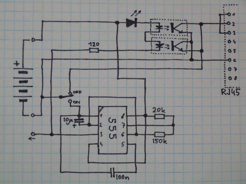
When the Rx and Tx pairs of the 10/100BaseT are connected together, they form a loopback. When connected to a network card or a switch port, the loopback sends the link beat pulses back to the port itself. The port then considers the connection to be active, and lights up the corresponding LINK light.
On a switch in the rack, there are two kinds of lights for each port: LINK, and ACTIVITY, or LNK and ACT. ACT tends to blink wildly with activity on the port, LNK is lit up when there is an alive connection with another Ethernet device and tends to be steadily on. Thus, a slowly blinking LNK light will stand out between the other lights. Periodically opening and closing the loopback does the job.
Experimentally it was found that a pair of optrons in antiparallel configuration of the output transistors can be used for closing the loopback with sufficiently low resistance. This was necessary because of the AC nature of the signal. The semiconductor structure of the transistor is typically asymmetric, thus even if the light opens the in both directions, resistivity of one of them is several times higher than the other one, which deforms the signal and may cause the switch to have problems recognizing the loop as closed.
For switching the circuit on and off, a bulletproof construction of an oscillator with a venerable 555 chip was chosen. The values of the components were calculated for a period of about 0.5 Hz, duty cycle approximately 1:1. The timing is not critical, the period has to be long enough to allow the switch to comfortably detect the closed link.
The power switch is connected to the output of the optrons, shorting them closed when the device is switched off. The device then serves as a "dumb" loopback. This allows improvised operation even when the batteries are dead.
The power is supplied by four AA cells, usually NiMH accumulators. This was chosen because of their easy availability in the field; in a bigger office at least somebody has a digital camera or a walkman with a set of those, which reduces logistical problems when your own batteries turn out to be dead. 9V cells are much more difficult to find between the people.
NOTE: Use 22 µF capacitor C2 instead of 10 µF one. Some switches havetrouble reacting sufficiently quickly to the closing/opening of the link.
Take your assistant, give him a phone or a transceiver. Stand at the rack with a piece of paper. Let the assistant walk from a socket to a socket, connect the device to every one of them, and watch the corresponding LNK light blinking on the switch; it should be the only one behaving this way, so it should stand out from the lines of LNK lights that are either dark or shining. Write down the socket number your assistant is at and the corresponding switch port. Repeat until the entire facility is mapped.
| R1 | resistor 120 Ω |
| R2 | resistor 20 kΩ |
| R3 | resistor 150 kΩ |
| C1 | capacitor 100 nF |
| C2 | capacitor 10 microF or 22 microF |
| U1 | timer chip NE555 |
| O1,O2 | optron PC817 |
| R1 | resistor 1.5 kΩ |
| LED1 | red LED |
| CON1 | connector RJ45 for cable |
| - | 4 1.2V AA NiCd cells, battery holder |
Put the device into a suitable box.
Test with various different brands of switches and network cards.
Design an alternative using only 2 AA cells.
Figure out if I can't use FET transistors instead of the optrons, which could
allow easy lowering of the necessary voltage. Alternatively, use high-gain
MOSFET optrons, which weren't used here because of their price. Use a
low-voltage version of the 555, or a voltage doubler chip.
Replace the optrons with a magnetic reed contact. Take a wind-up mechanism from a clock or a toy, put magnets on the wheel of suitable speed, generate the on-off signals as the wheel rotates across the reed relay.
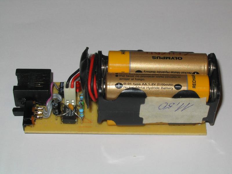 Unit assembled with batteries. | 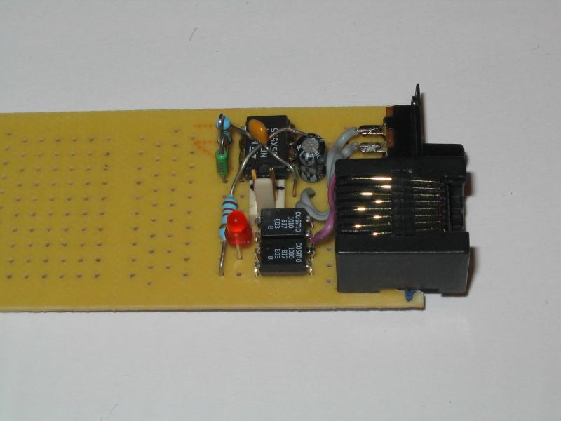 Detail of the device. | 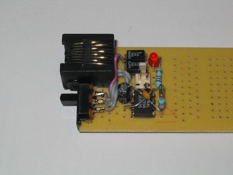 Detail of the device. | 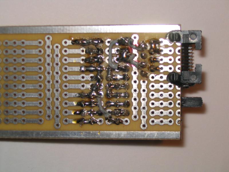 Detail of the circuitboard. |