 was desired for the lab. A fused filament fabrication was chosen on the
basis of wide availability of the technology and the feedstock materials and its relative maturity.
was desired for the lab. A fused filament fabrication was chosen on the
basis of wide availability of the technology and the feedstock materials and its relative maturity.
A 3D printer was desired for the lab. A fused filament fabrication was chosen on the
basis of wide availability of the technology and the feedstock materials and its relative maturity.
After some abortive attempts to build from scratch, it was decided to build from a kit.
Due to the high speed of the actuators, a delta variant was chosen instead
of the classical Carthesian positioning.
Due to good experiences from another facility that obtained
a Kossel Mini model, a vendor was chosen. So, a Kossel XL kit was obtained from a web shop.
The Kossel XL is a relatively large machine:
hot end
NEMA17, with 52/11:1 (57:11) ratio
The kit came in the form of two large flat boxes, and a tube. The tube housed the long parts, the cut-to-length OpenBeam extruded profiles. The boxes contained everything else - the 3D-printed plastic parts, carbon fiber composite tubes for the delta assembly, the joints, the motors, the timing belts, the hot end, the bed and its heater, and the electronics.
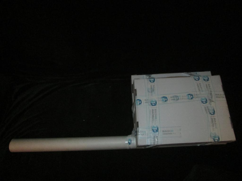 As-received | 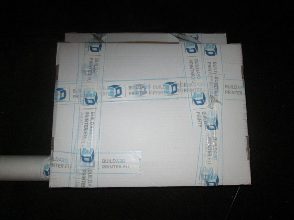 As-received | 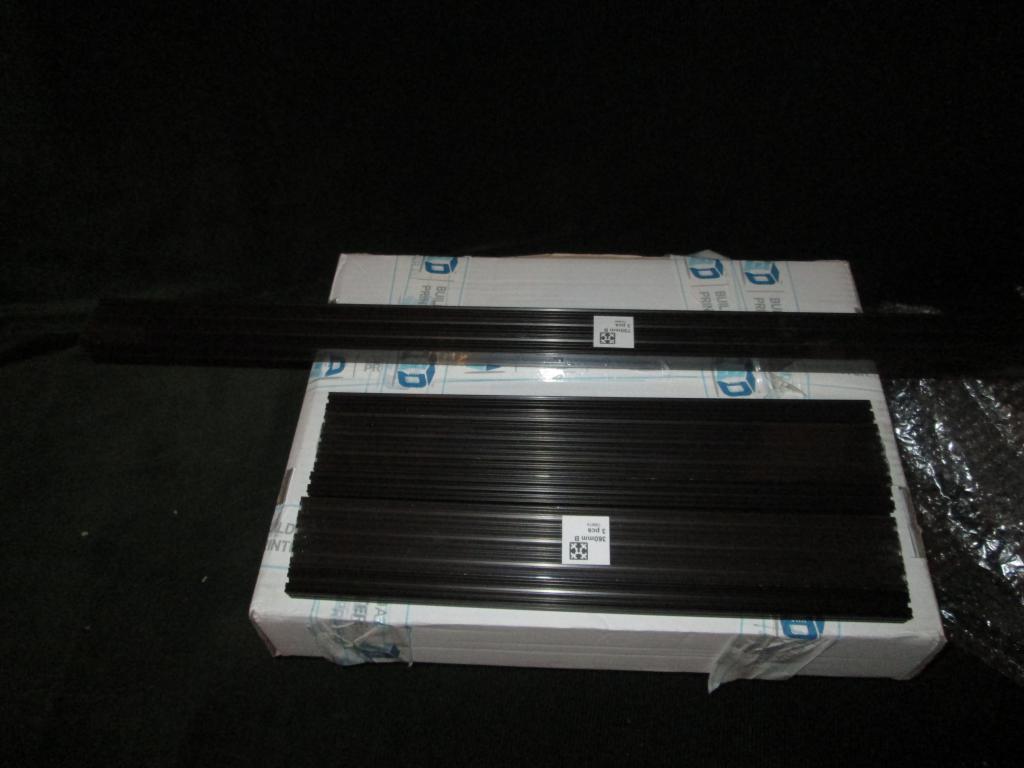 Beams | 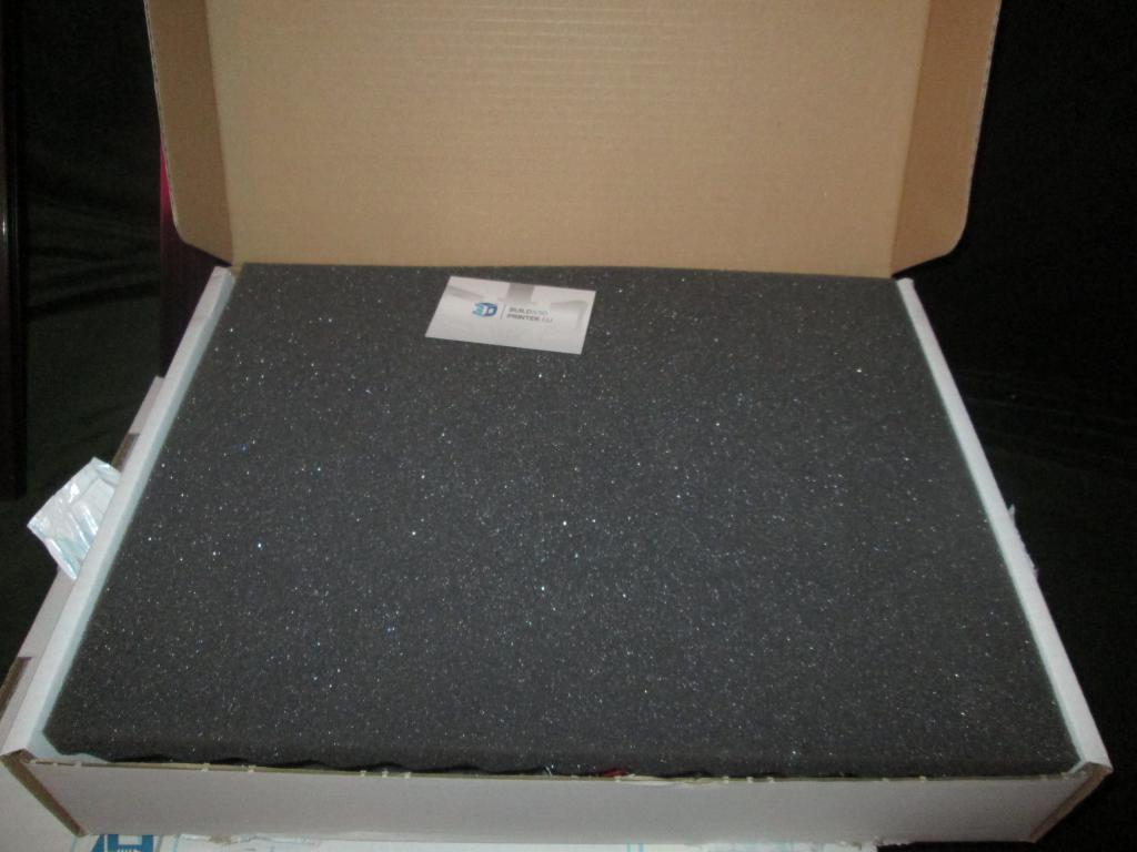 Box content |
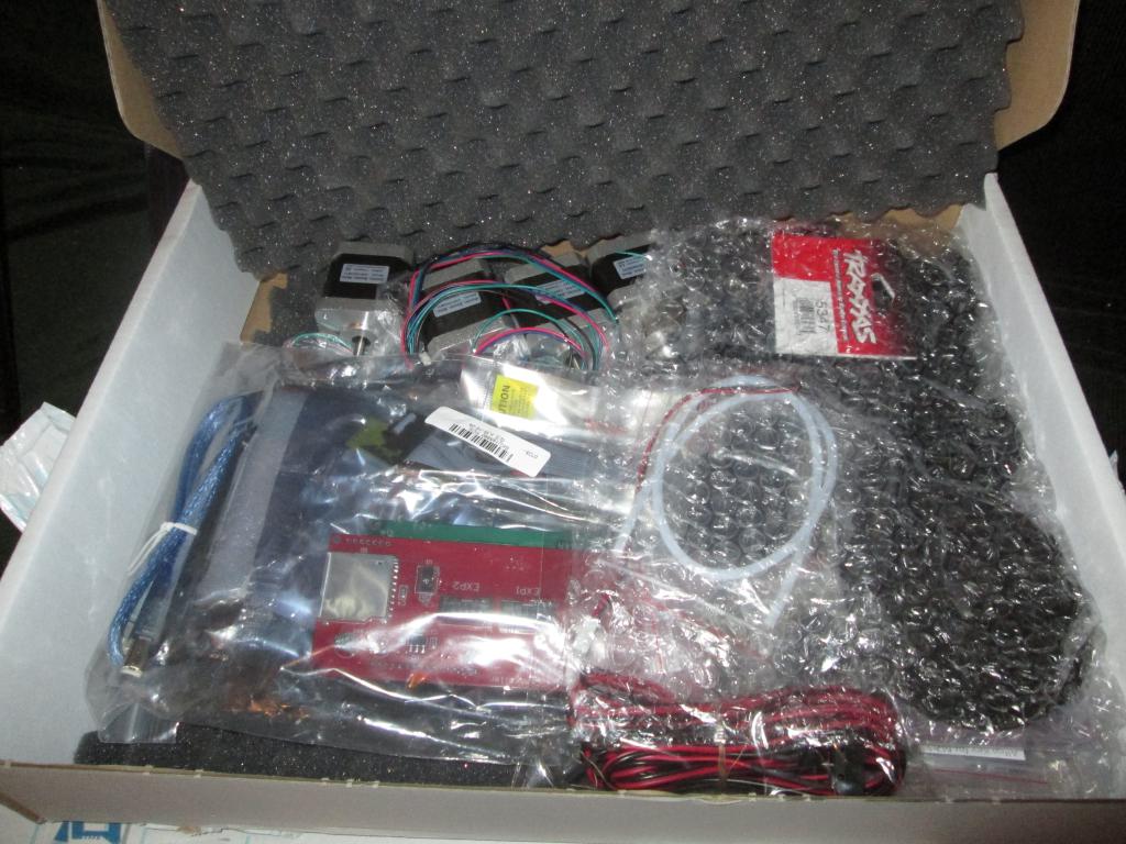 Box content | 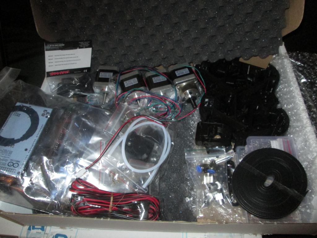 Box content | 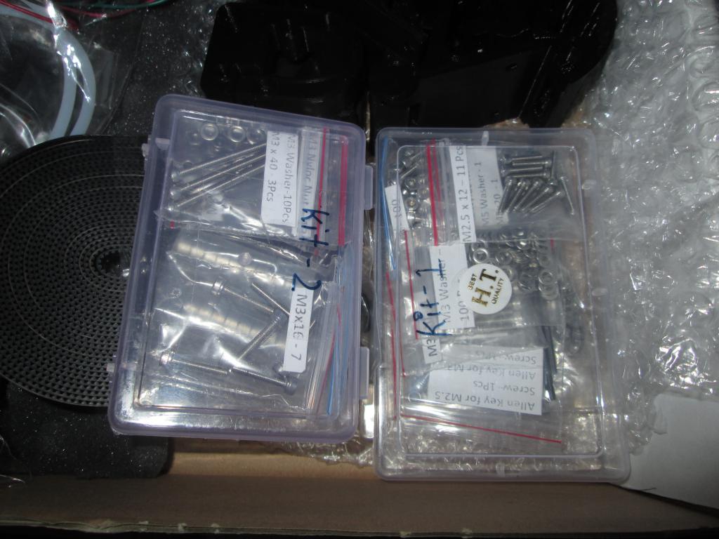 Box content | 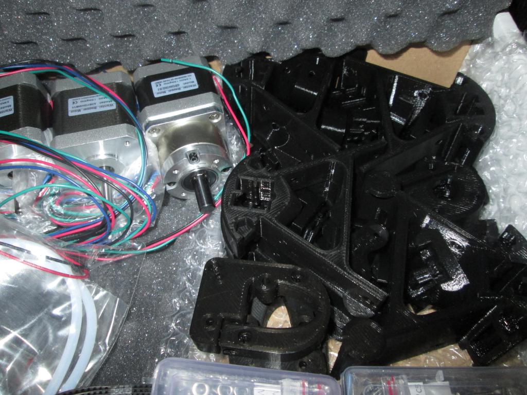 Box content |
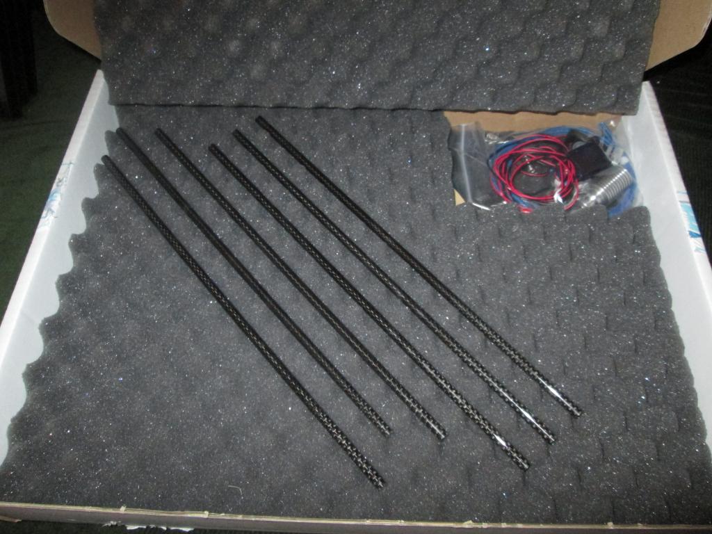 Box content | 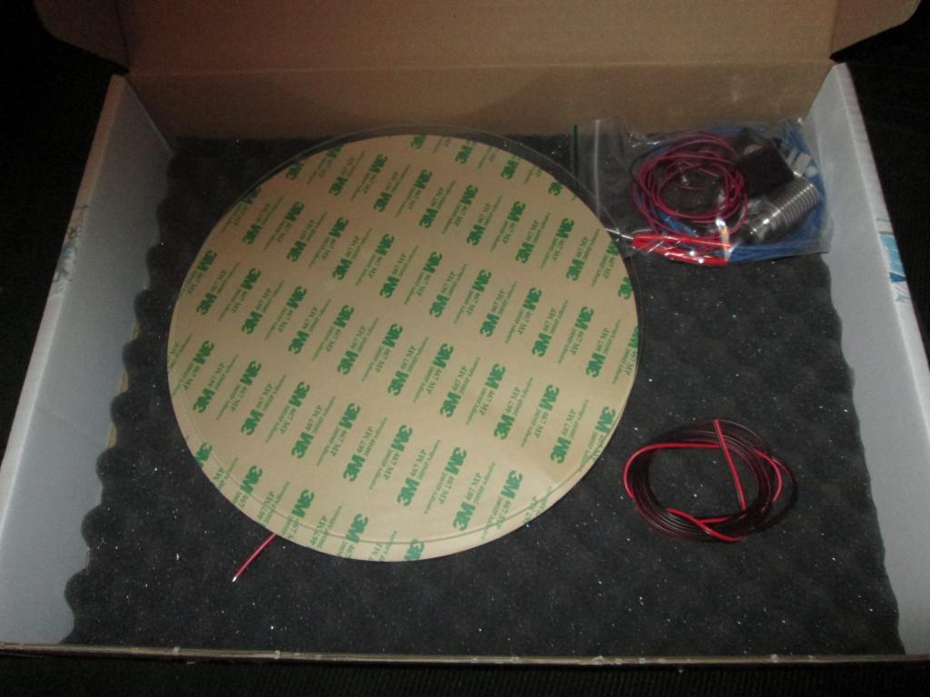 Box content | 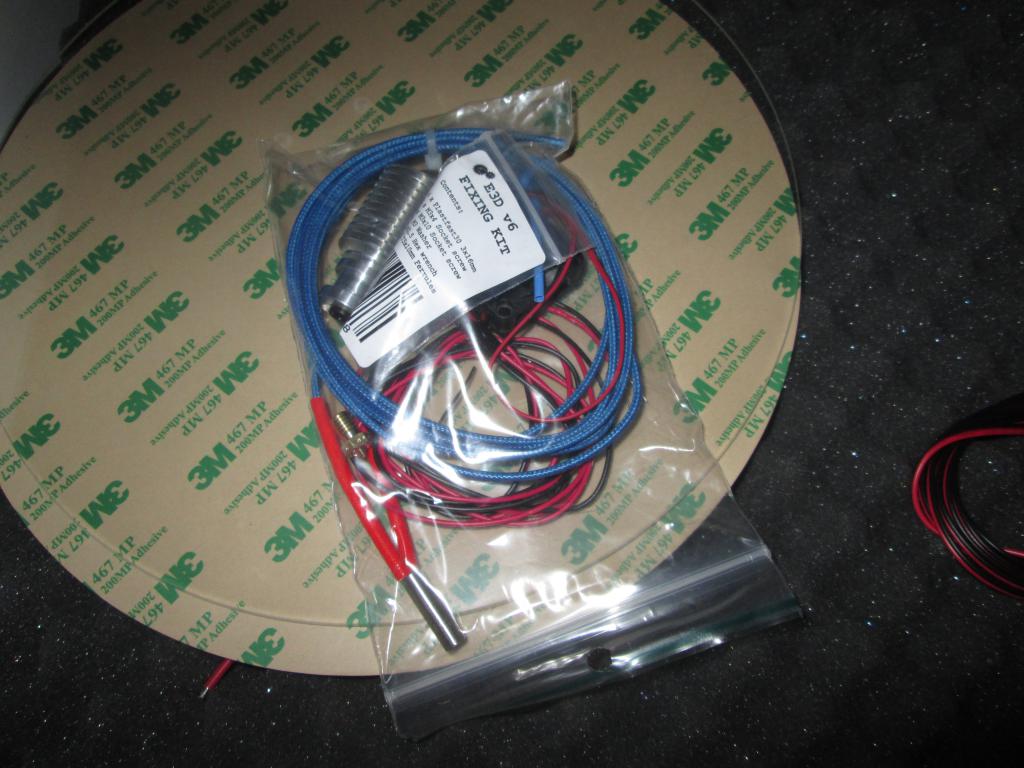 Box content | 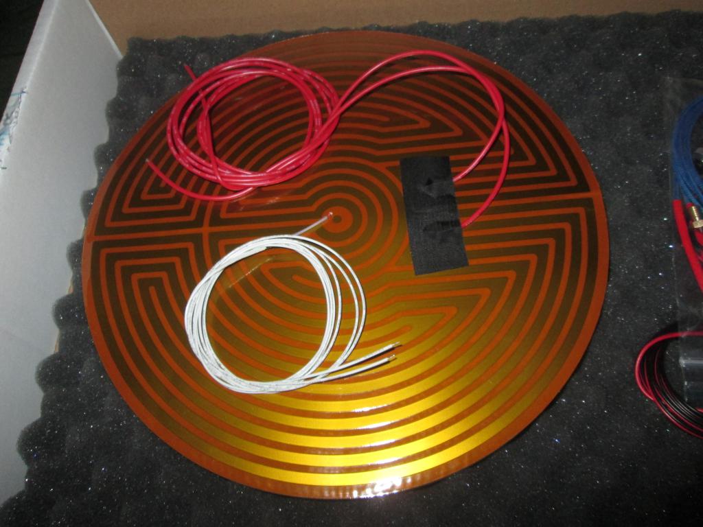 Box content |
The vendor instructions were
generally followed. Only the differences and snags will be described here.
http://builda3dprinter.eu/build-manuals/kossel_mini_build_manual/start-building/lower-frame-v2-2/
The round antilifting pads were cut from the bottom motor mounts. This was done with a boxcutter knife; flush-edge
wirecutters would be better, as a small injury was obtained when the knife slipped, the material is fairly tough even in
single layer. The holes in the triangles were redrilled to 3mm diameter.
The GT2 pulleys were attached to the motor shafts. The motors were attached to the frame.
A pair of short beams was attached to each motor mount, to one side; screws were inserted through the holes, nuts placed to their ends, then the beams slided on the nuts and the screws were loosely tightened. The motors hindered accessibility of the screws.
Some nuts were inserted to the beams, to facilitate mounting of other equipment to the sides of the frames.
Screws were placed to the other sides of the mounts, and nuts attached. The three subassemblies were placed on a flat table and slid together; the screws on the fixed sides had to be loosened a bit, to allow more movement of the beams. The screws then were tightened.
The kit is designed around hex-head M3 screws. The tool that comes with the kit is an Allen wrench
of the appropriate size. In its stock form, it is too long to comfortably reach into some tighter areas,
especially in the triangular areas. To make the work less difficult, part of the key was cut off with a Dremel wheel.
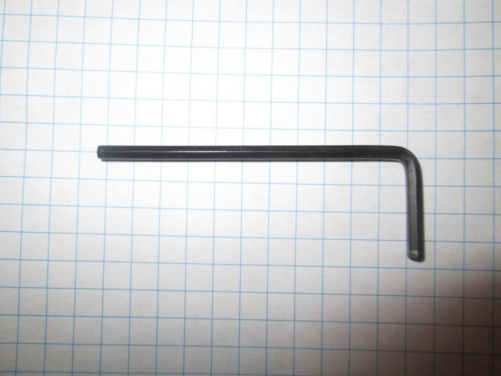 Allen key | 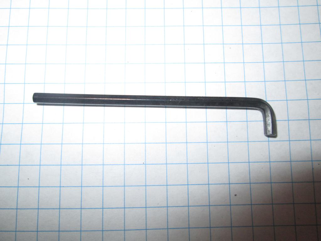 Allen key, shortened |
http://builda3dprinter.eu/build-manuals/kossel_mini_build_manual/start-building/upper-frame-2/
The antilifting pads were cut off from the top idler mounts. Holes were drilled to 3mm diameter.
The flanged F623ZZ bearings were found in the boxes, after some searching (they ARE in the package, hiding in another bag.) The top idler assembly was put together.
Horizontal rails were added, to one side of each part. The parts were placed on a flat table and slid together, like the bottom frame. Before the assembly, some spare nuts (2+2+4) were inserted to the sides of the beams.
http://builda3dprinter.eu/build-manuals/kossel_mini_build_manual/start-building/vertical-carriages/
The holes were drilled to 3mm. The carriages were assembled uneventfully. The nuts did not hold in the holes but could be reinserted later, after the rollers are placed in. Even the one hole that's half-hidden under the wheel is accessible.
The holes in the mount plates were drilled to 3mm and the mount plates attached to the carriages. The nuts for their holes aren't needed until now.
http://builda3dprinter.eu/build-manuals/kossel_mini_build_manual/start-building/build-diagonal-arms/
The Traxxas rod ends came with M4 bolts without heads. The bolts were screwed into the rod ends,
about halfway. The rod ends are made of tough plastic that holds the thread well.
The carbon rods were already of proper length. The insides of the ends were cleaned and roughened with a thin round file, just to be sure. Metal-filled epoxy was used to glue the M4 bolts protruding from the Traxxas ends into the ends of the rods. The assembled rods were left on a pair of parallel long beams to hold their ends off the table, in equal distance and parallel, until the epoxy set.
The little metal centers were snapped into the rod end pads. They don't go in entirely willingly, some gentle force is needed. A pair of pliers will do a good job here. It can be done with a thumb against the table, but it hurts.
The push-fit connector instruction does not apply to the J-end head.
Drill all holes, horizontal and vertical, to 3mm diameter.
The diagonal rods were attached to the platform and the carriages.
http://builda3dprinter.eu/build-manuals/kossel_mini_build_manual/start-building/build-extruder/
The extruder uses a motor with planetary gear. This gives the extruder a lot of push force and avoids skipping steps.
The end of the gearbox shaft was modified to facilitate manual turning of the extruder.
The spur gear was attached to the geared stepper shaft.
The printed part contains a plenty of support material in the hole for the idler bearing. This is a major hindrance, a knife cuts the material poorly; a Dremel mill had to be used carefully. It is needed to remove a little extra material around the edges of the top and bottom of the hole, to facilitate free rotation of the bearing.
The center hole for the spur gear was enlarged a little with a Dremel mill (a round file may do) as the fit was a bit too tight around the spur gear.
The bearing was inserted and put in place. It has to be ensured that it can rotate freely.
Attach the extruder assembly to the geared motor. There are four ways; pick the one where the motor cables won't be in the way of anything.
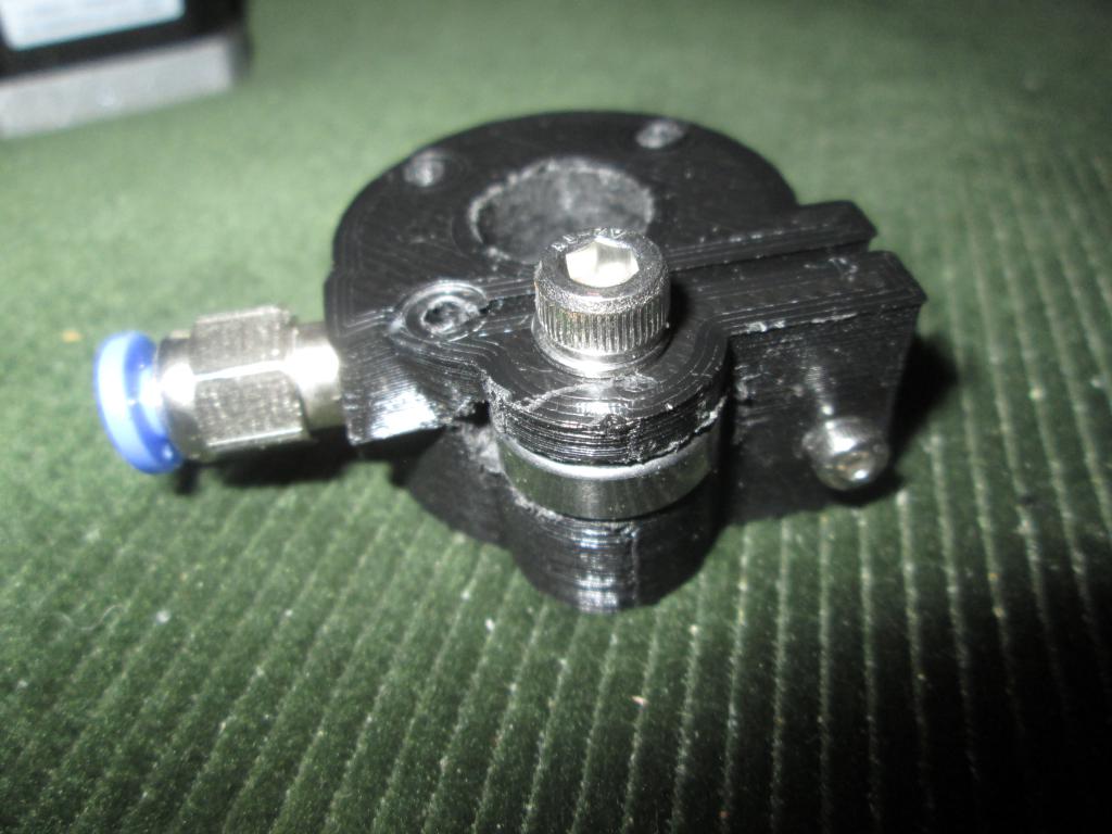 Extruder assembly, problematic part |
Sometimes it may be needed to move the filament manually, without assistance of the electronics (when it is nonfunctional or the printer is depowered). A Dremel wheel was used to cut a groove in the top of the shaft, before the spur gear was attached. This groove can be use for turning the shaft with a large flat screwdriver, if the need arises, and for easier visual monitoring of the shaft position changes.
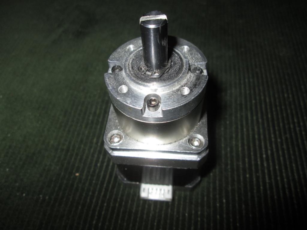 Extruder motor end cut | 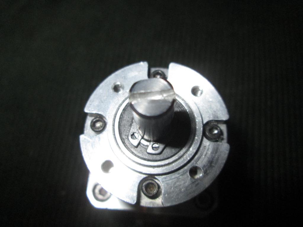 Extruder motor end cut | 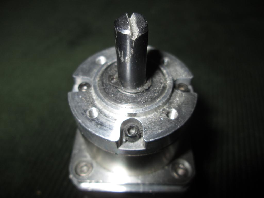 Extruder motor end cut |
Hot end was assembled. The little thermistor is tiny and its wires are thin; do not break them. Use crimp tube to attach the longer cables, as a solder could melt in extreme situations.
The vertical beams were placed into the mounts of the bottom frame; a pair of screws with nuts was placed in their holes before they were pushed in. They went in with major difficulties and needed to be hammered in. To facilitate later disassembly, it may be good to push the beam in and pull it out a few times.
The carriages on the spider assembly were slid to the sides of the beams.
Several nuts were placed to each slit of the vertical rails. They won't be accessible later, better have spares.
Endstop switches were attached to their mounts and slid onto the inner sides of the vertical beams.
The motor mount was slid on the back of a vertical beam.
The bottom edges of the beam holes of the top frame were chamfered with a dremel. The top frame was placed on top of the beams and hammered in, then pulled off, then hammered on again, to facilitate the removal later.
The timing belt was pulled over the motor wheel and the top idler and through the twist channel in the carriage, and cut to length, with just a bit of reserve. One end was placed to the belt coupler. The belt was pulled tight, the last few teeth were cut off so the other end of the well-pulled belt can be slid into the coupler.
Coupler clamps were slid over the couplers and tightened.
The bed holders were attached to the bottom frame.
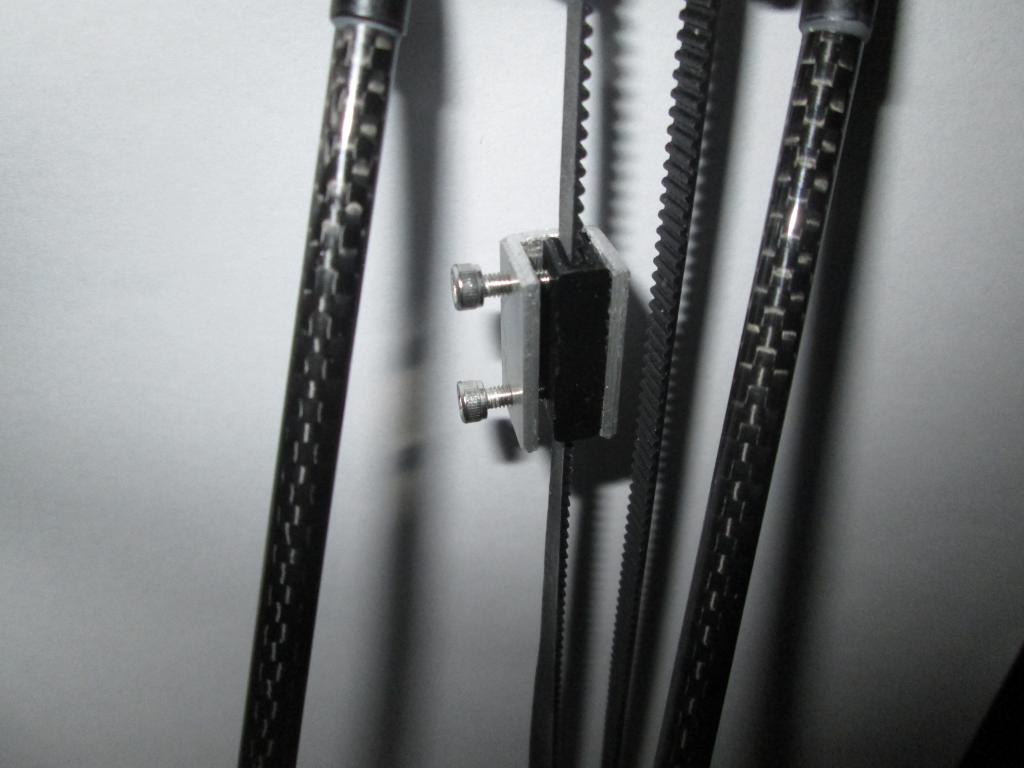
The stock belt coupler does not hold the timing belt well enough. The vendor instructions suggest using zip ties
to keep it clamped together. This was found to not be desirable for multiple reasons - the clamp force is low and the zip ties
are consumables, eaten during each change.
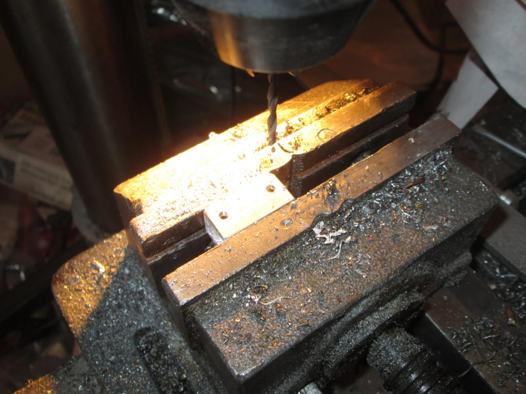
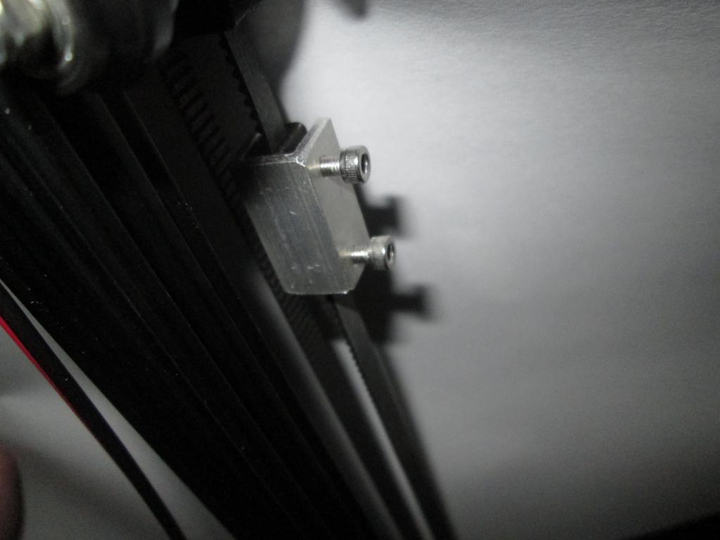
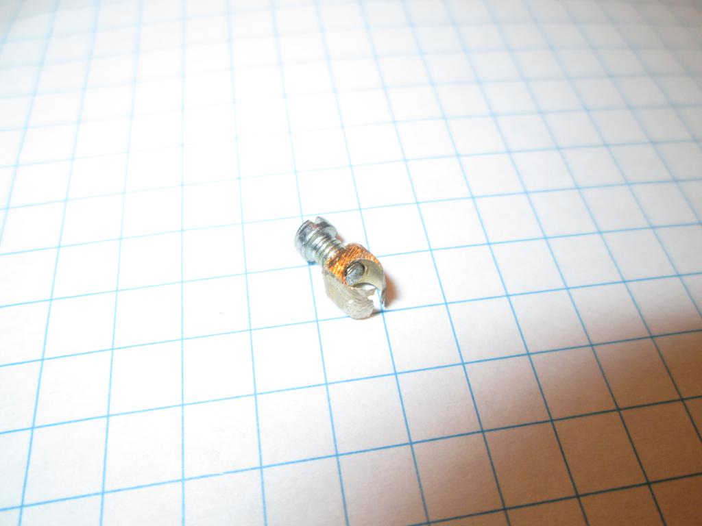
An add-on clamp was engineered from a 12x12mm, 2mm thick aluminium U-profile. A 25mm length, matching the length of the stock coupler, was cut. A pair of 2.5mm holes was drilled, to match the positions of the centers of the belt ends in the clamp, and M3 thread was cut in them.
After installing the belt in the coupler, the clamp was put over the coupler and the screws tightened. This provided very firm hold of the belt.
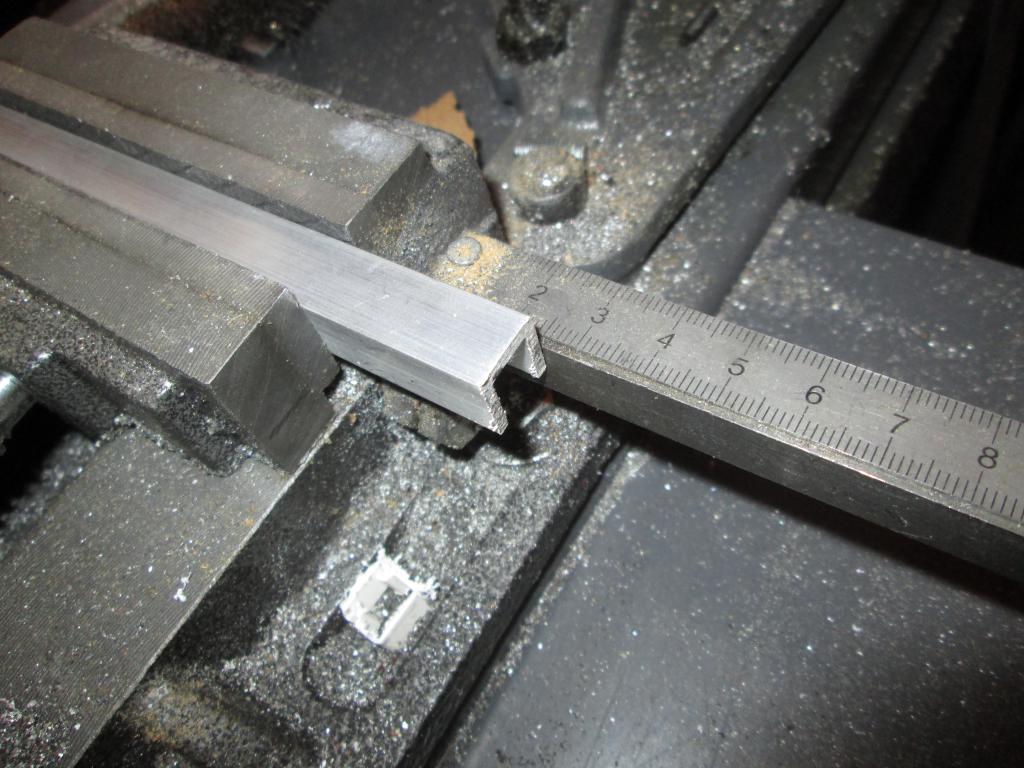 Belt coupler clamp | 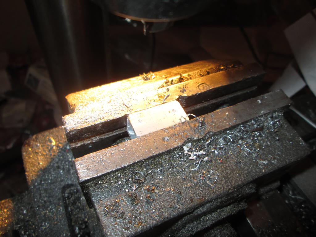 Belt coupler clamp | 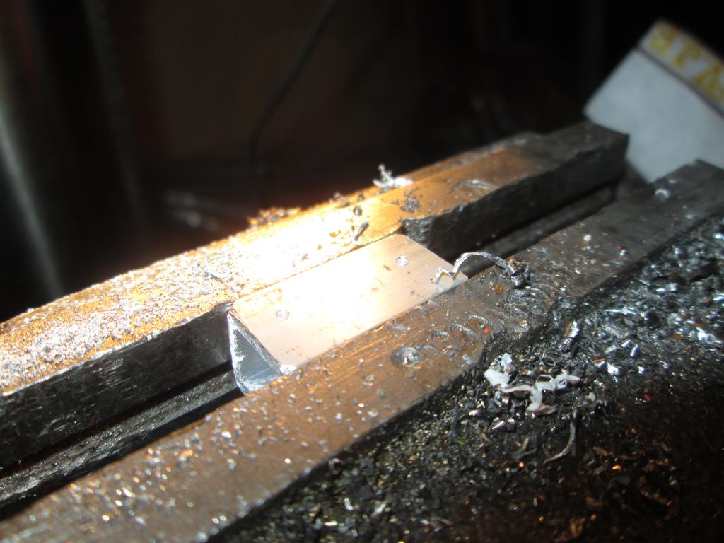 Belt coupler clamp | 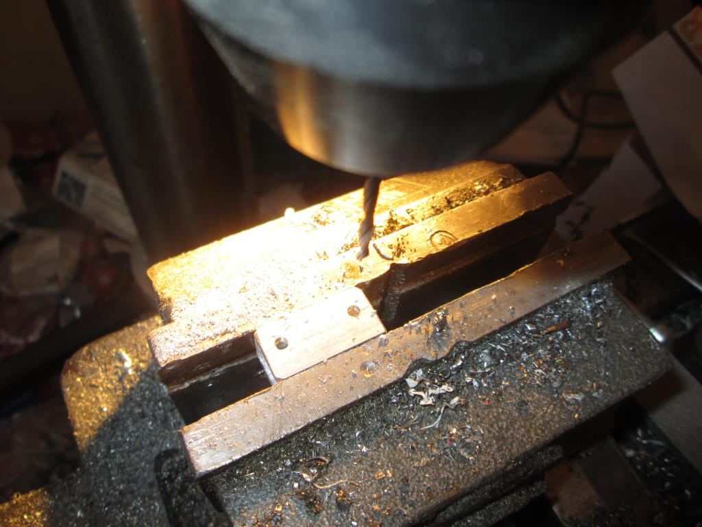 Belt coupler clamp |
 Belt coupler clamp | 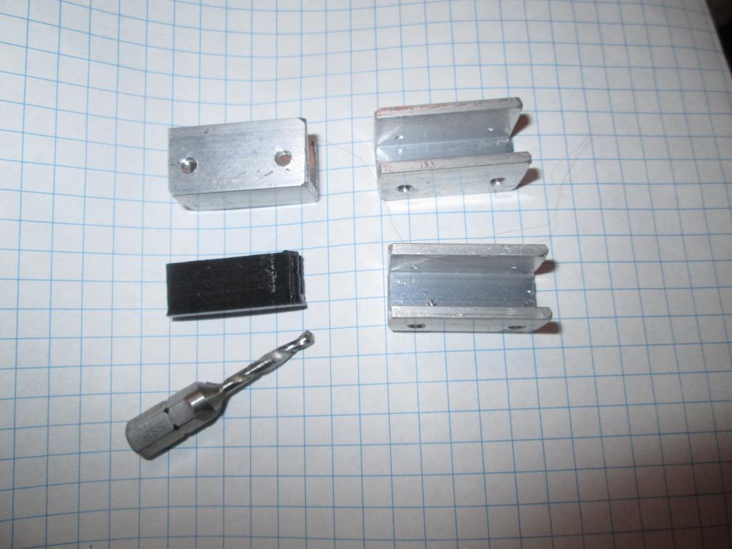 Belt coupler clamp | 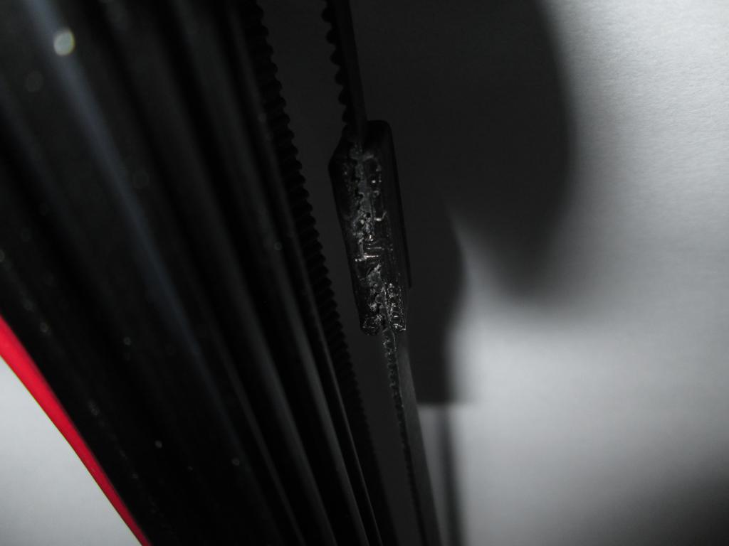 Belt coupler clamp | 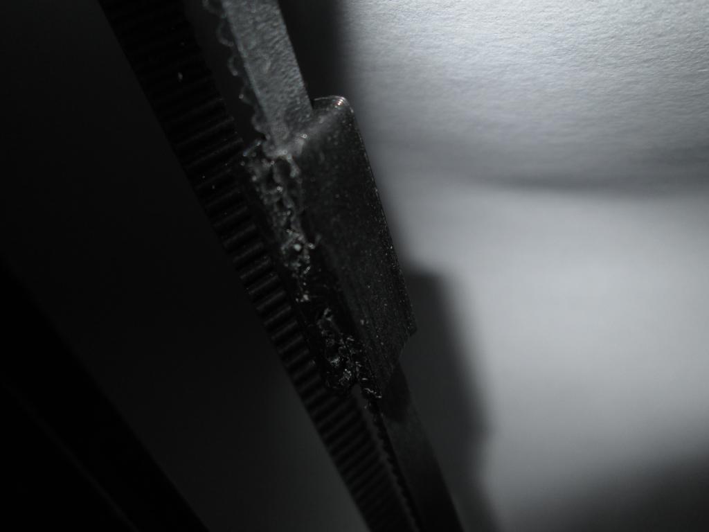 Belt coupler clamp |
 Belt coupler clamp | 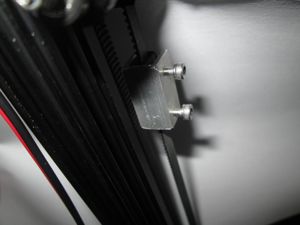 Belt coupler clamp | 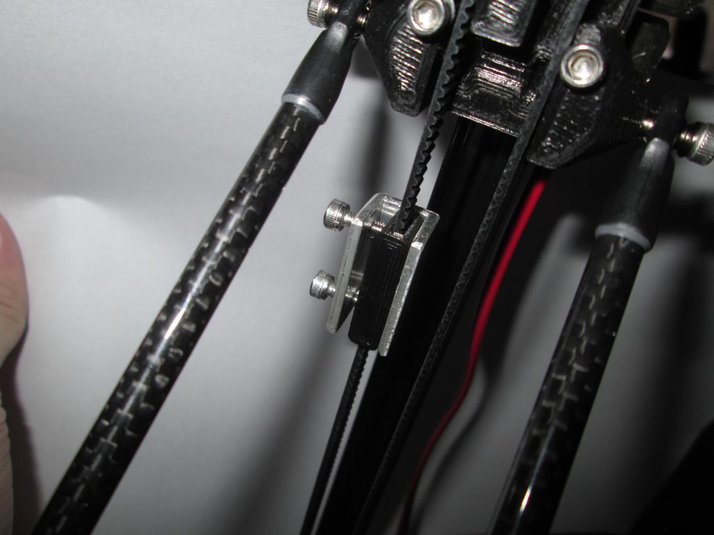 Belt coupler clamp | 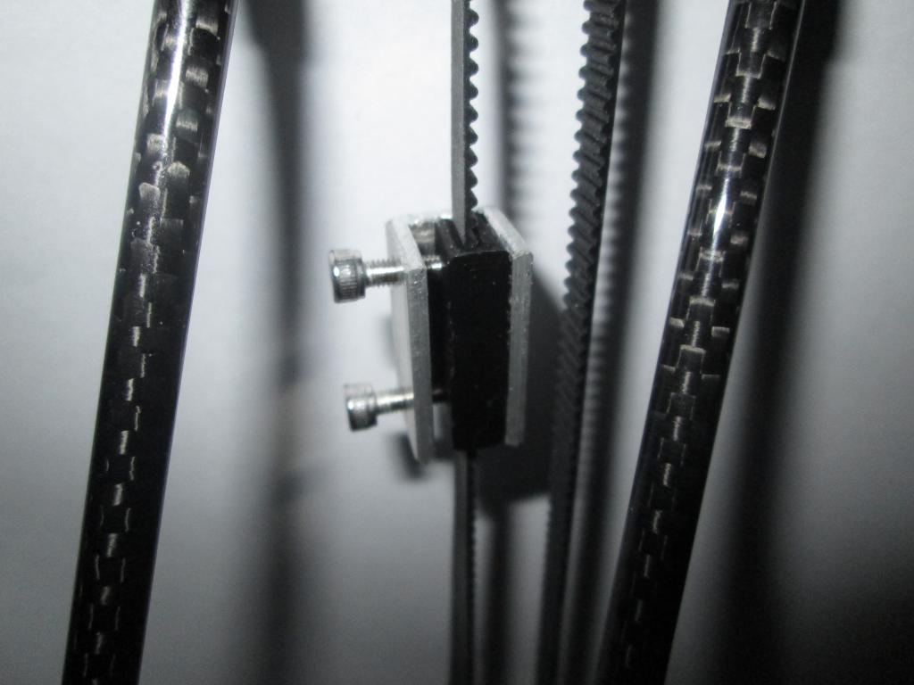 Belt coupler clamp |
 Belt coupler clamp |
The probe was assembled. The Allen wrench prescribed in the manual was not long enough to match the all-metal hot-end. A different design was attempted but later abandoned because of the seizing of its rod.
This part of design was abandoned for now. Force-sensitive resistors or another kind of probe will be done later.
 Autoleveling probe parts | 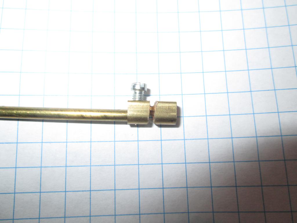 Autoleveling probe parts | 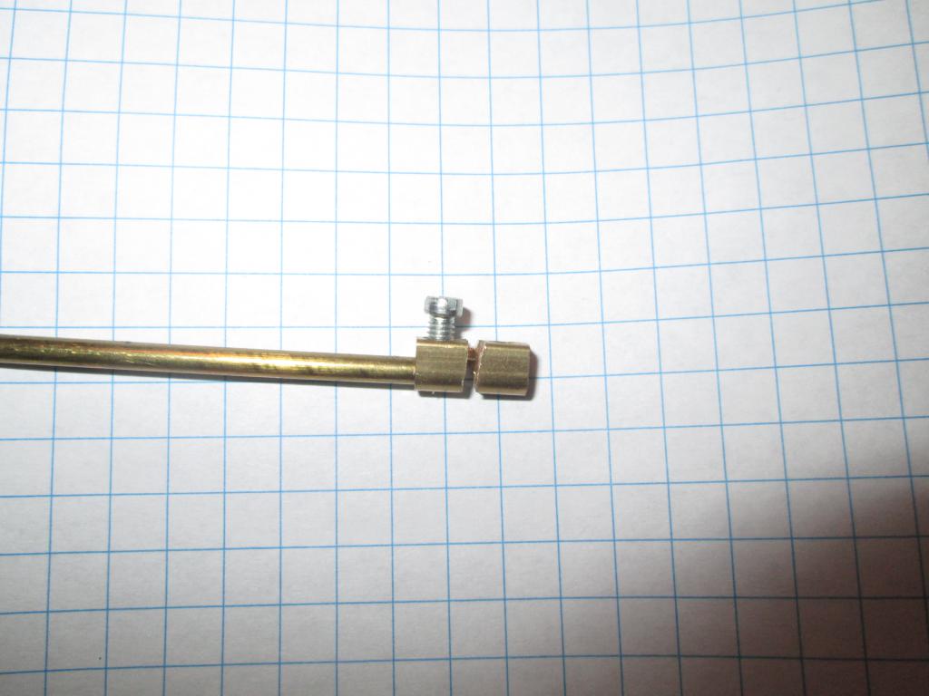 Autoleveling probe parts | 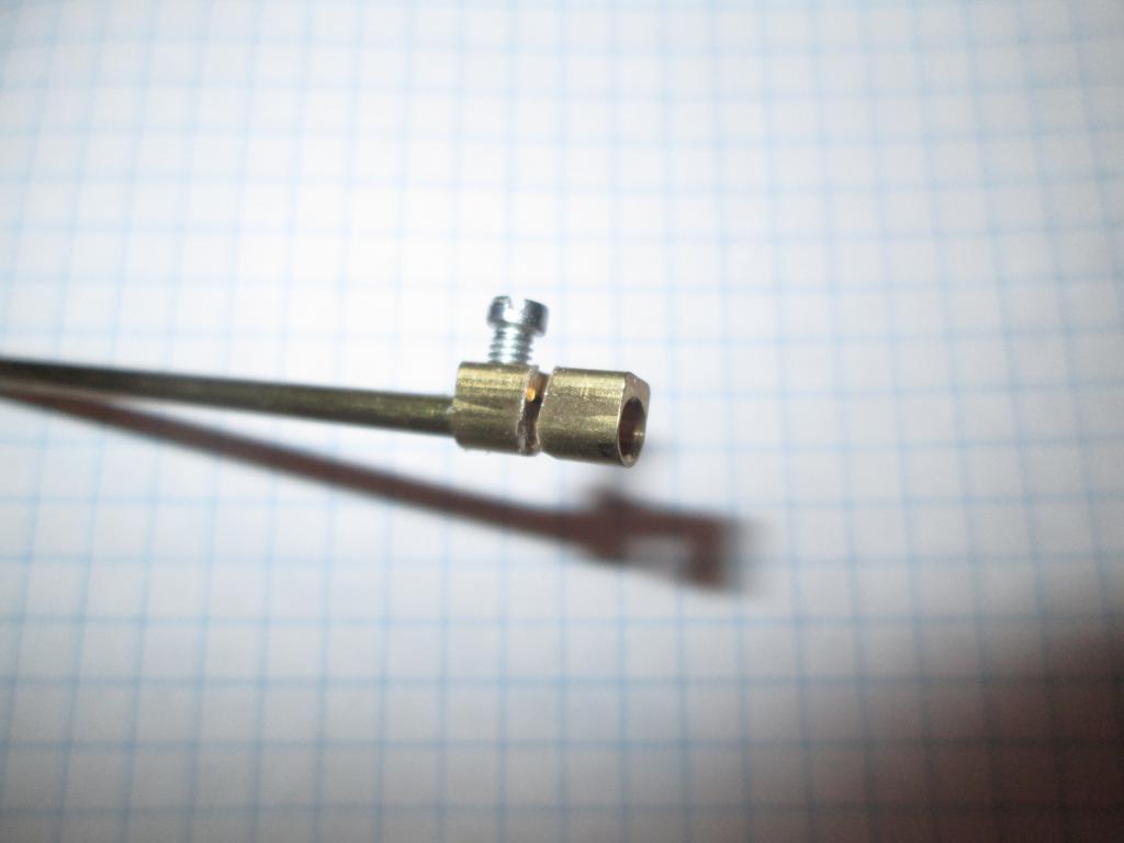 Autoleveling probe parts |
 Autoleveling probe parts | 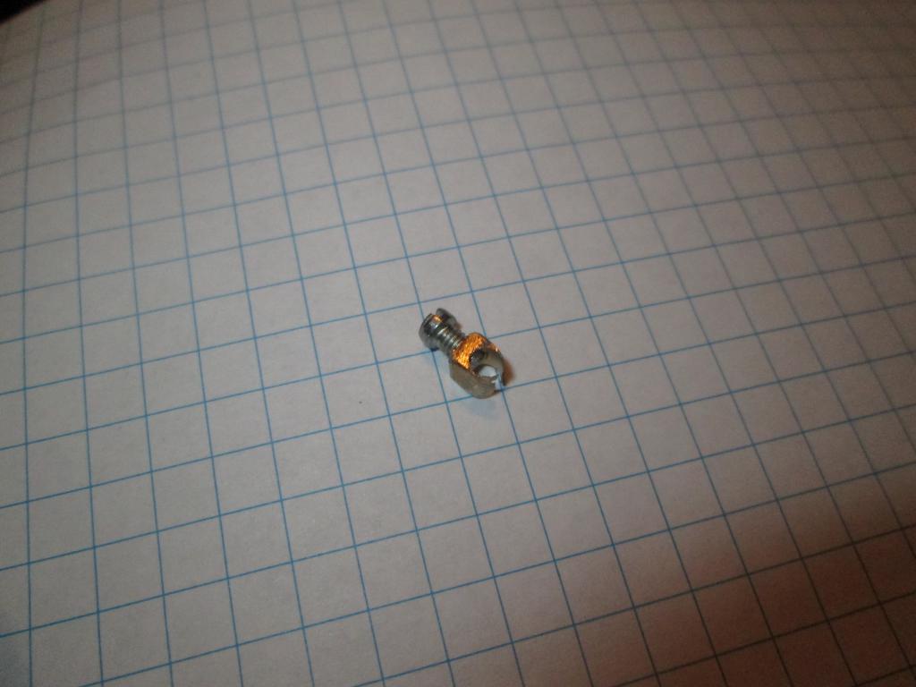 Autoleveling probe parts |
http://builda3dprinter.eu/build-manuals/kossel_mini_build_manual/start-building/build-electronics/
The RAMPS board was placed on the Arduino board.
The stepper rate was set to 1:16 with the jumpers, for each of the motors.
Heatsinks were attached to the stepper driver chips and their litle boards were placed in the RAMPS sockets. Beware to maintain the correct orientation.
Connectors were attached to the ends of the stepper cables and the endpoint switches, and to the leads of the hot-end thermistor. The electronics was placed under the glass bed, for the sake of testing.
Take a multimeter. Measure the voltage between the current adjustment trimpot center and the ground.
Turn the trimpot until 0.5 volts is reached. Repeat for each driver board.
DO NOT FORGET THIS!
A 12-to-19 volt adjustable universal laptop power supply was used for powering the assembly.
The controller board is powered from both the USB and the 12V power supply. Either one is sufficient to make the controller and display alive. The 12V power is however necessary for motors and heaters and motor drivers.
The firmware is the interface between the stepper motors, extruder, hot end, and other actuators, endstop switches, thermistors, and other sensors, and the host computer.
The controller board is based on an Arduino Mega board, with a RAMPS stepper controller shield. Other combinations are possible and used in various other printers.
There is a range of offers for the controller firmware.
Based on advice the Marlin firmware was chosen.
The firmware was downloaded from the developer github site.
The Marlin-Release-1.0.2 was decided against because of lack of support for autoleveling in delta kinematics.
The newest dev version, at that time MarlinDev-dev-20150910, was chosen.
The Windows Arduino dev environment was used for configuration and compiling of the firmware.
Functional configuration for Kossel XL, Marlin-dev-20150910, SD card is disabled in this configuration:
Pronterface was chosen as the control software. It allows acting as a g-code
terminal. This is important for calibration.
The manual iterative M665/M666 method was used, similar to here:
http://reprapandme.blogspot.cz/2014/02/first-tests-and-calibration.html
Raw notes:
   - Leveling: use the M666 for xyz offsets, iteratively level the points next to the towers
     set the machine height to a bit bigger value than the machine is
     set the offsets to a negative value, then pick the smallest value (here Yoffs) as reference
     and don't touch it and add the differences of the (X-Y) to the current Xoffs


   > M666 x-2.1 y-0.7 z-5.1
   - x=16.1 y=15.6 z=17.7
   > M666 x-1.6 y-0.7 z-3.0   (-2.1+(16.1-15.6), -0.7+(15.6-15.6), -5.1+(17.7-15.6))
   - x=15.4 y=15.4 z=15.9
   > M666 x-1.6 y-0.7 z-2.5
   - x=15.4 y=15.4 z=15.7
   > M666 x-1.6 y-0.7 z-2.0    (this time used twice the delta)
   - x=15.4 y=15.4 z=15.4 (LEVELED!) => 0=14.9
    -- Increasing DELTA_SMOOTH_ROD_OFFSET lowers the hotend.
    -- M114 -> position, XYZ counts
    -- M501 -> show settings
    -- DELTA_RADIUS = DELTA_SMOOTH_ROD_OFFSET - DELTA_EFFECTOR_OFFSET - DELTA_CARRIAGE_OFFSET
    -- M665 L<delta diagonal> R<delta radius> S<segments per second>
   > M665 L333.00 R174.10 S125.00 (default)
   - xyz=15.4 0=14.9 -> decrease DELTA_RADIUS
   > M665 R172.0
   - xyz=15.8  0=14.7 (wrong direction, difference is increasing)
   > M665 R178
   - xyz=14.2  0=15 (way too much)
   > M665 R175.5
   - xyz=14.9 0=15 (just about)
   > M665 R175
   - xyz=15  0=14.9
   > M665 R175.25
   - xyz=14.9 0=14.9  (acceptably perfect) (x,y,z,xz,yz=14.9, xy=14.7 - problem?)
   --> H=270-14.9=255.1
   - workflow: - calibrate endstops, so x=y=z
               - calibrate radius, so (x=y=z)=0 (both will change with tweaking the value, converge it)
               - calibrate z-height (easiest)
Raw notes:
   - extruder configuration:
   -- real: 3mm for 15mm set, reversed run
      gearbox 57/11, wheel diameter 12mm, 200 steps, 16x microstep -> 200*16*57/11=16581.8 steps/rot, steps_rot/(12*pi)=440.07 steps/mm
      real measured=449.0 steps/mm (extruded 100mm, measured 98 mm, adjusted)
      store M92 E449.0


   - hot end configuration:
   -- heater PID autotune: M303 E0 S200 C8    (extruder 0, 200 °C, 8 cycles)
      PID Autotune finished! Put the last Kp, Ki and Kd constants from below into Configuration.h
        #define  DEFAULT_Kp 44.46
        #define  DEFAULT_Ki 5.73
        #define  DEFAULT_Kd 86.24
   -- also, can be set via M301 P44.46 I5.73 D86.24
   -- PID autotune finished (this time repeated for 190 °C, and with extruder full of filament, previous test was empty
        #define  DEFAULT_Kp 41.21
        #define  DEFAULT_Ki 4.66
        #define  DEFAULT_Kd 91.11
   -- also, can be set via M301 P41.21 I4.66 D91.11
   -- beware of fan clip position on the heatsink! put it towards the top, at the bottom it overcools the nozzle
The workpiece sometimes needs to be cooled. For that purpose, a fan is usually attached to the hot end.
This however requires thermal insulation to be applied to the heater and nozzle, to avoid thermal losses there. The stock heater is somewhat underpowered for that purpose.
Photos should be added here.
The additional workpiece-cooling fan was also cooling the nozzle heater block. This caused additional energy expense, the nozzle got underheated, the heater could not cope, and the thermal protection tripped after a few minutes.
The heater had to be insulated.
[link?:Ceramic fiber wool], soaked with [link?:water glass], was applied to the surface of the heater block and let to dry. The resulting material is brittle but highly refractory.
Other insulation materials are possible for the future.
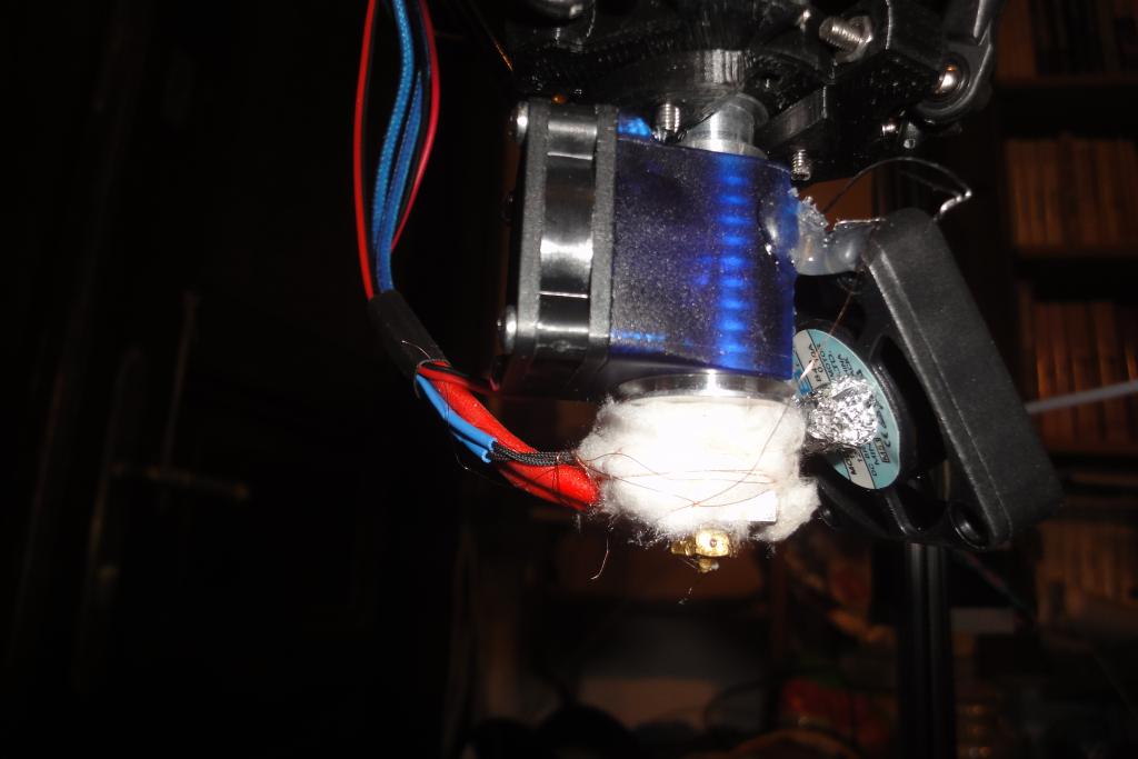 Head thermal insulation | 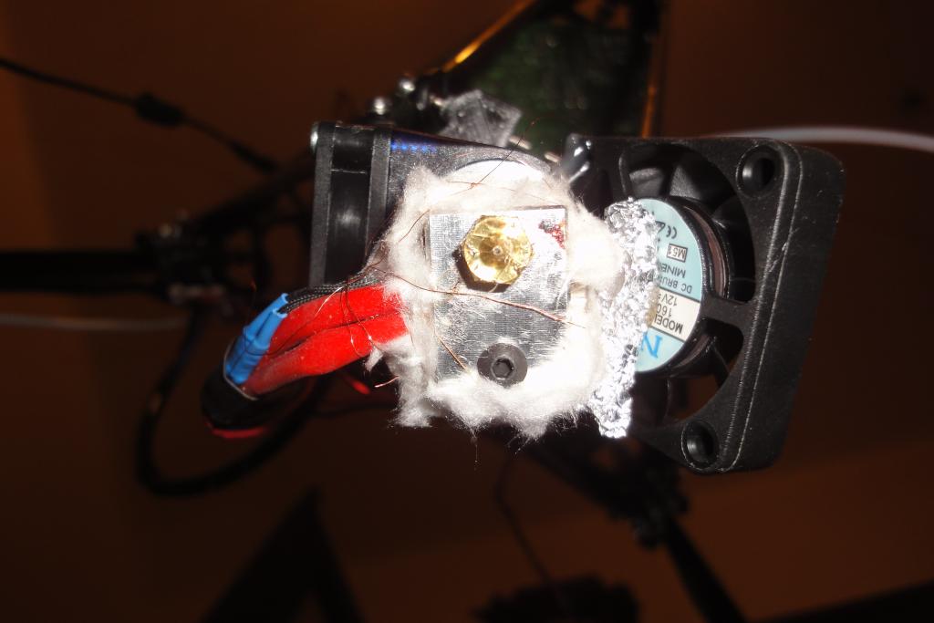 Head thermal insulation | 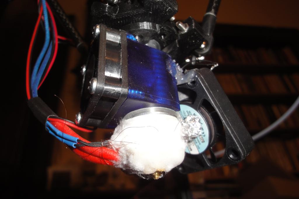 Head thermal insulation |  Head thermal insulation |
 Head thermal insulation |  Head thermal insulation |  Head thermal insulation |
The position of the controller board and stepper drivers under the heated bed was judged to be suboptimal due to the poor thermal design.
A triangular board with cut off edges was cut from a sheet of circuitboard-like material; a depopulated board from a junked TV was used. Grooves were cut to the edges, and screws with large washers were used to attach the board from the bottom side of the top frame.
Holes were drilled to match the Arduino board, M3 screws were installed to them, and the board was attached to the screws.
A wire harness between the stepper motors and the controller board was made, from 3x4 lengths of wires. Fairly thick cables were used to minimize their resistance.
The controller display was temporarily attached to the front rail of the top frame.
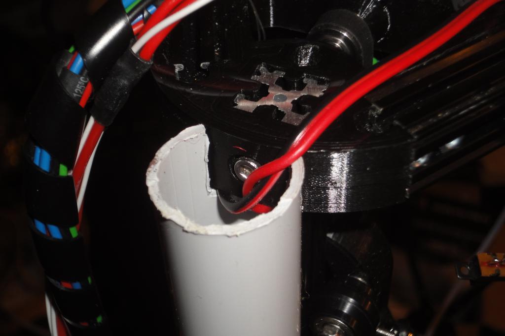
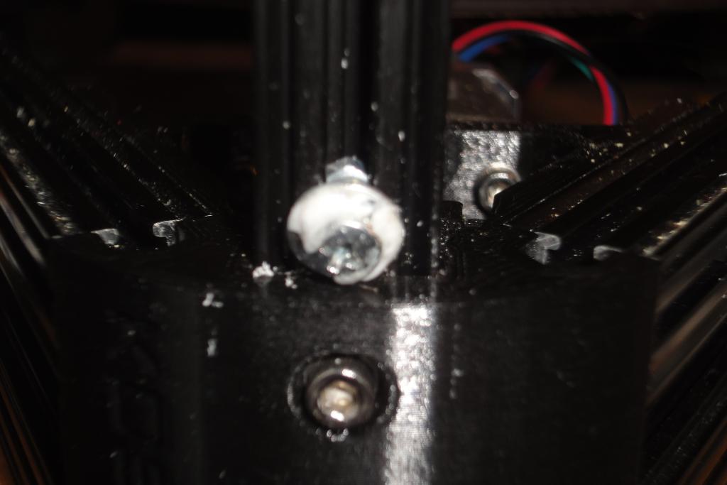
A length of plastic pipe was used to organize the cables between the top and the bottom end. A 25mm diameter pipe was cut to length matching the machine height minus the width of one rail. Cutouts were made to match the top and bottom mounts of the idler and the motor. Grooves were made for screws; getting the screws with washers on the OpenBeam rail to the tube was a bit challenging. A washer may have to be glued to the screw head, as otherwise it will keep slipping between the tube and the beam instead of getting to the inner side of the tube.
The tube was mounted in place with a pair of screws. The motor harness was pulled through. The wires for the heated bed and its thermistor were also pulled through. This allows a neat, clean wiring.
The tube is hopefully big enough for also a mains power cable and an Ethernet cable; the cabling from the power supply and the host computer board should be placed there as well, and terminated on a box on the bottom side.
The tube is also sufficiently rigid and sufficiently accurate to serve as an additional mount for clamps with other equipment attached; e.g. a webcam.
 Wire cover tube, top end | 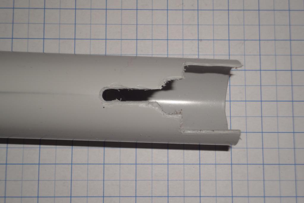 Wire tube, end | 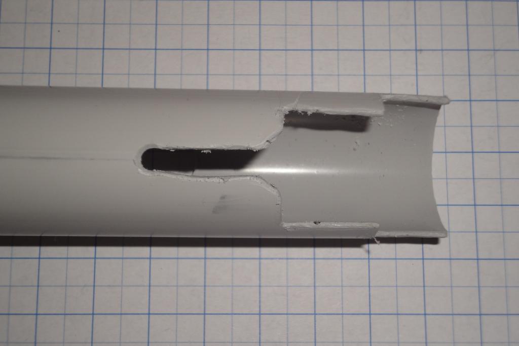 Wire tube, end | 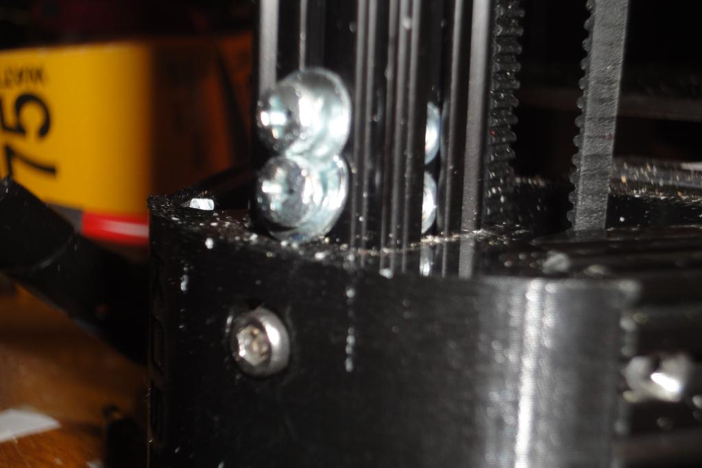 Wire tube screws |
 Wire tube end | 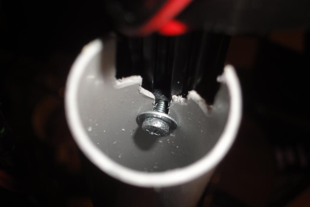 Wire tube, screw attachment | 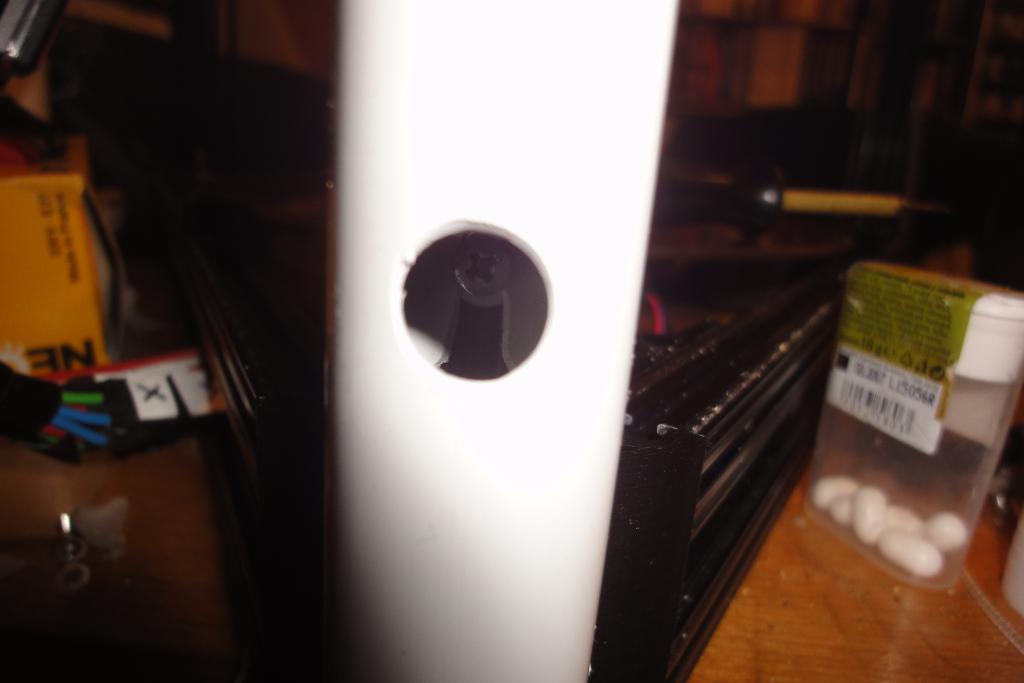 Wire tube, screw attachment, wrong nut position | 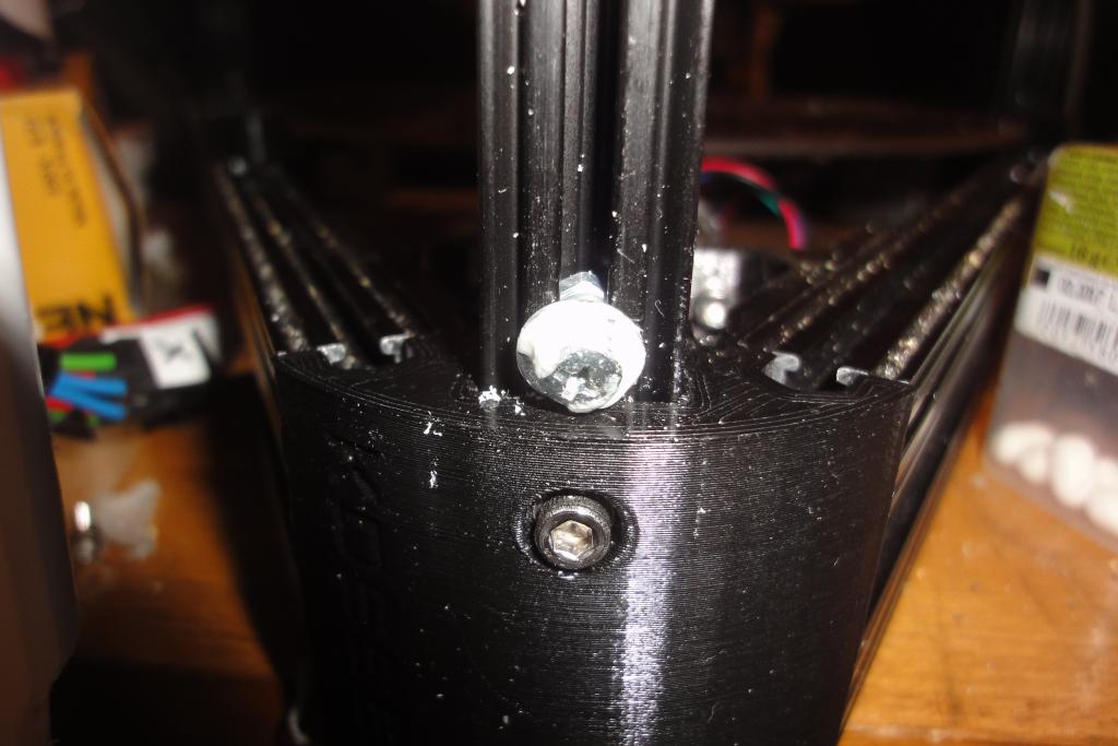 Wire tube, screw mount |
 Wire tube, screw mount | 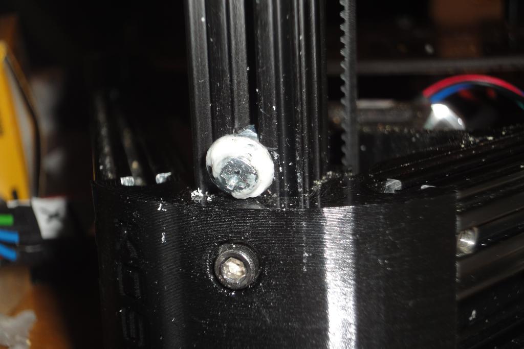 Wire tube, screw mount | 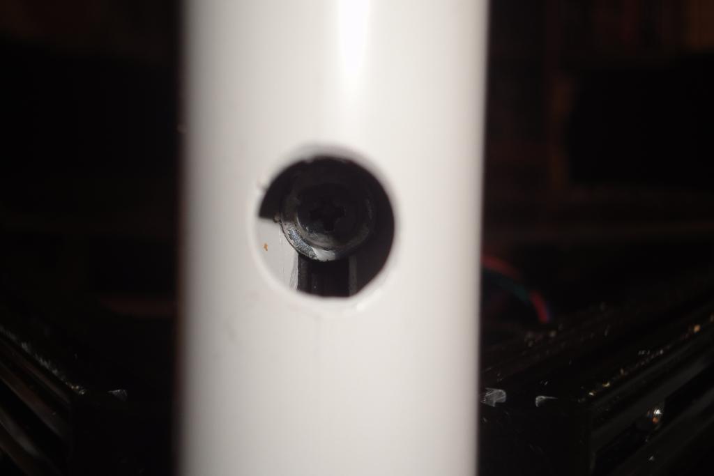 Wire tube, mount screw in place | 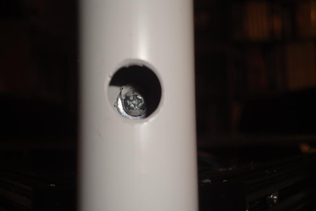 Wire tube, mount screw in place |
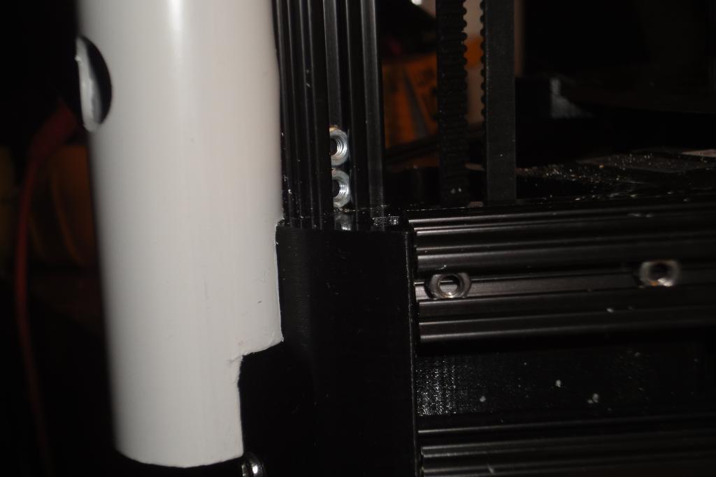 Wire tube in place | 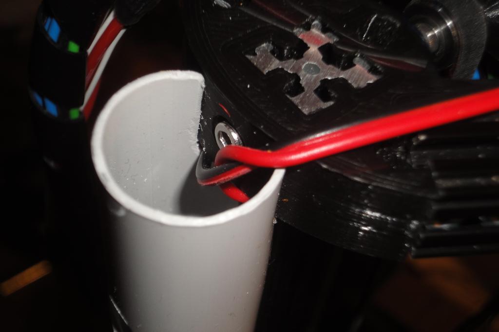 Wire tube in place |
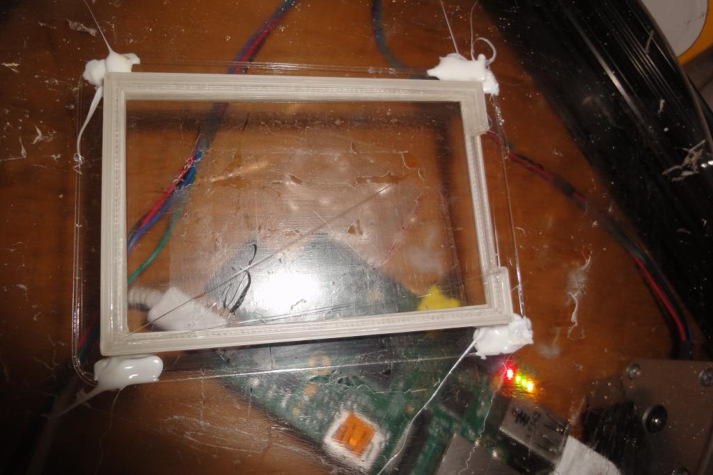
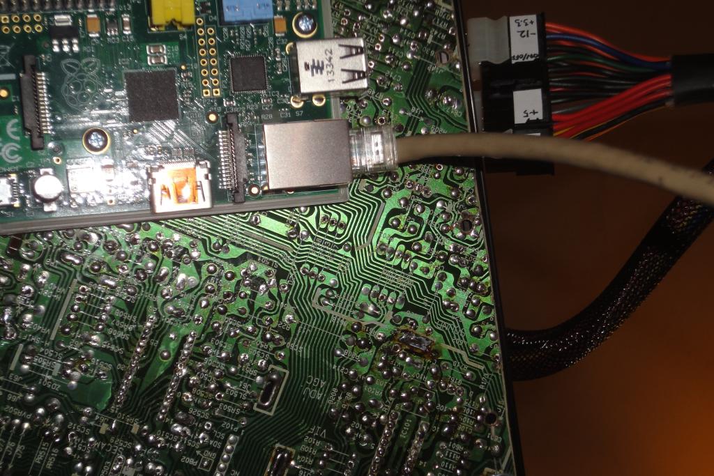
A Raspberry Pi embedded computer was chosen to run the printer. The board was attached
to a custom printed frame from the bottom side of the top-frame mount plate.
The board was powered from the +5V standby power rail. The chosen PSU has 2 amp capability on this rail, which fully satisfies the 0.3 amps the board actually needs.
 Raspi mount frame | 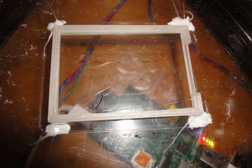 Raspi mount frame | 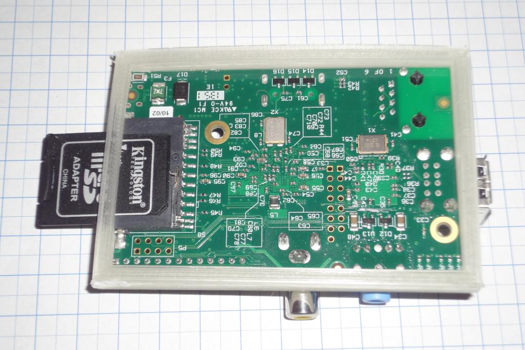 Raspi mount frame | 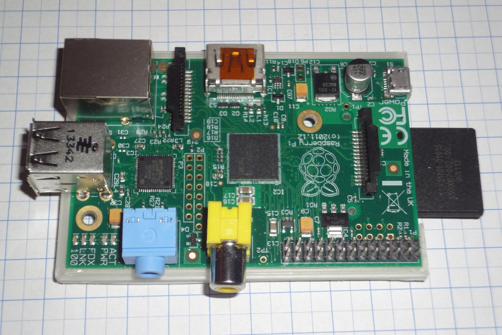 Raspi mount frame |
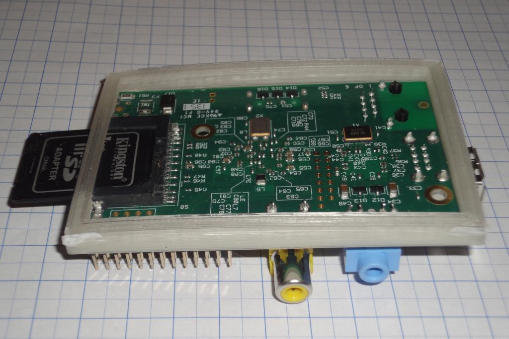 Raspi mount frame |
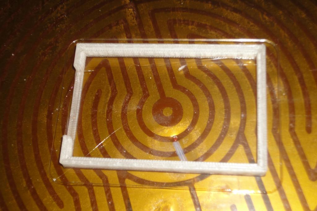 Raspi mount frame, printed with heated bed | 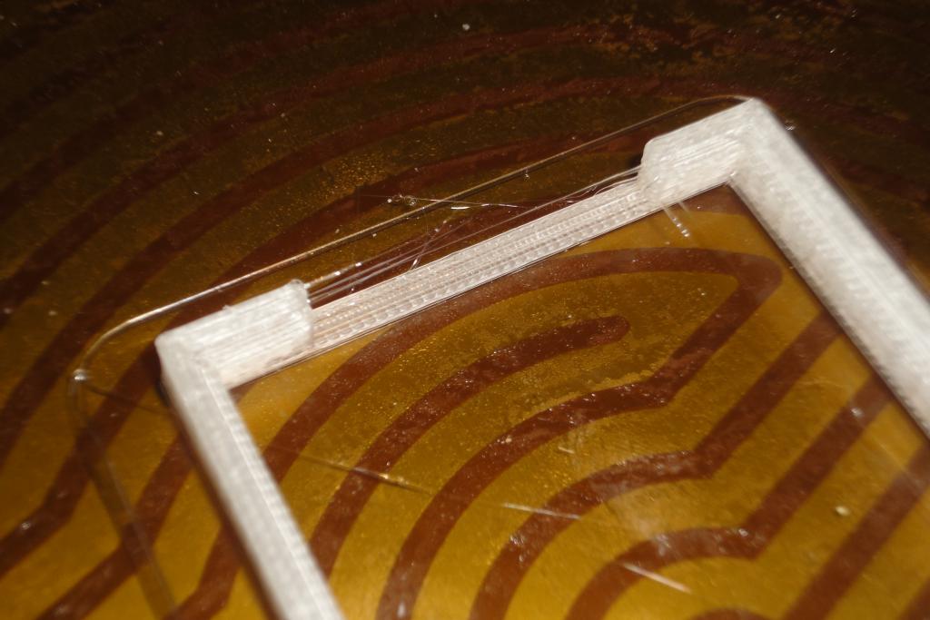 Raspi mount frame, printed with heated bed | 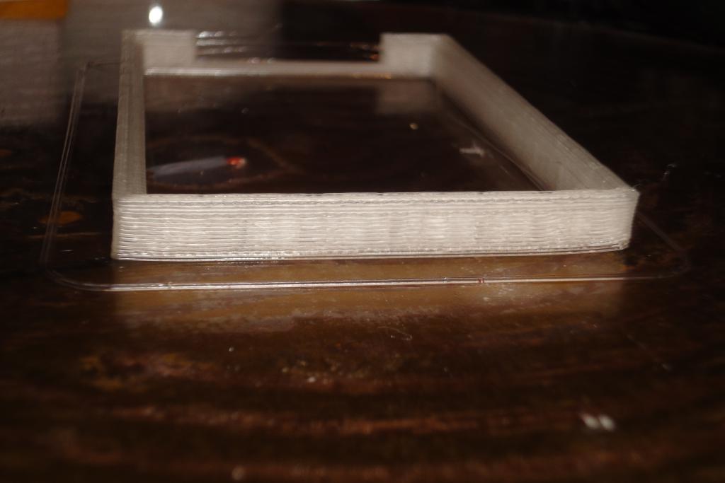 Raspi mount frame, printed with heated bed | 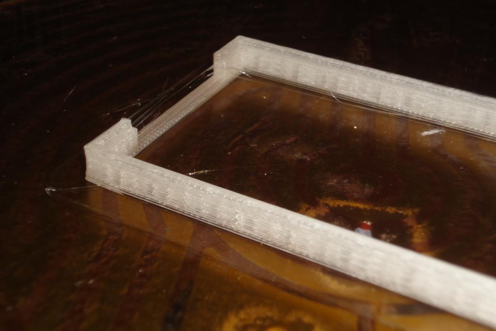 Raspi mount frame, printed with heated bed |
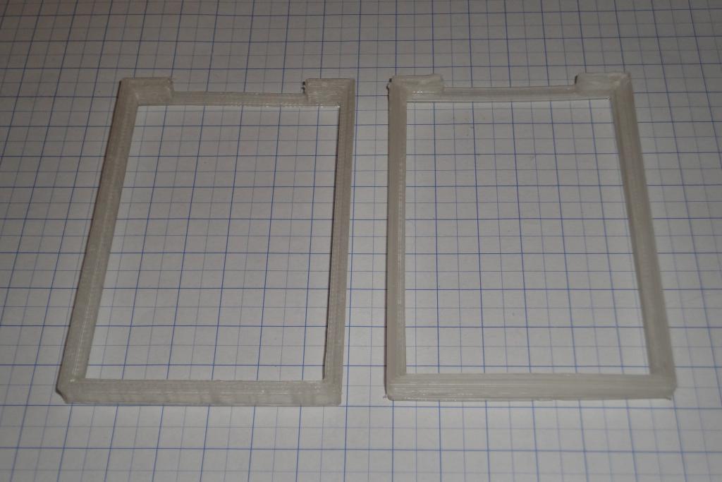 Raspi mount frame, printed with and without heated bed | 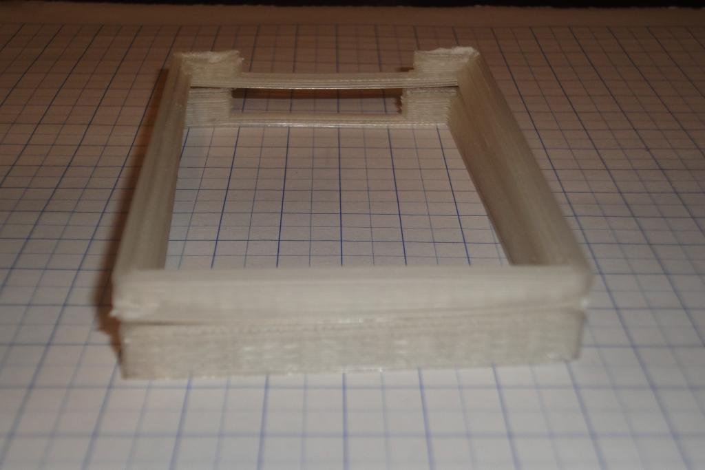 Raspi mount frame, printed with and without heated bed | 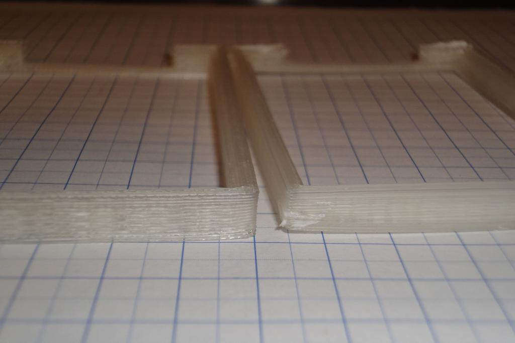 Raspi mount frame, printed with and without heated bed | 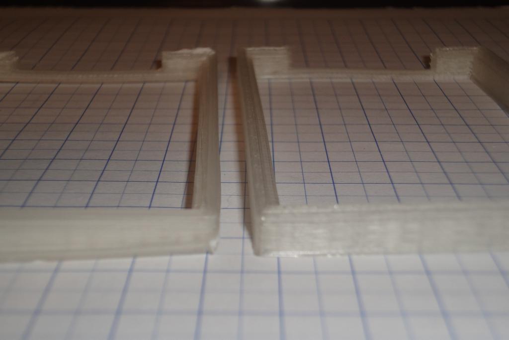 Raspi mount frame, printed with and without heated bed |
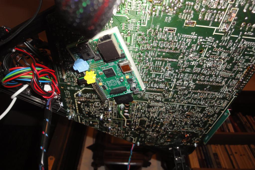 Raspi mount | 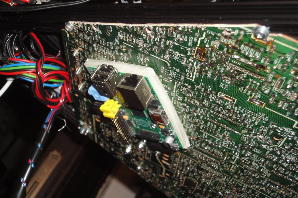 Raspi mount | 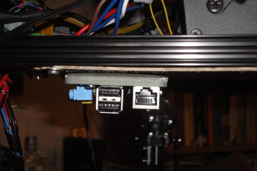 Raspi mount | 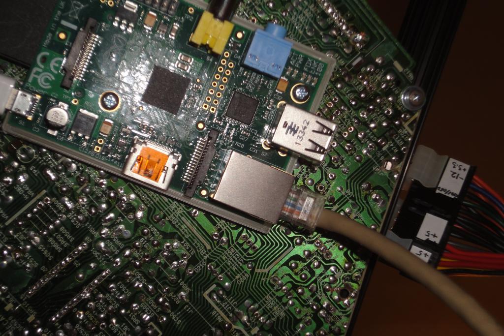 Raspi mount |
 Raspi mount | 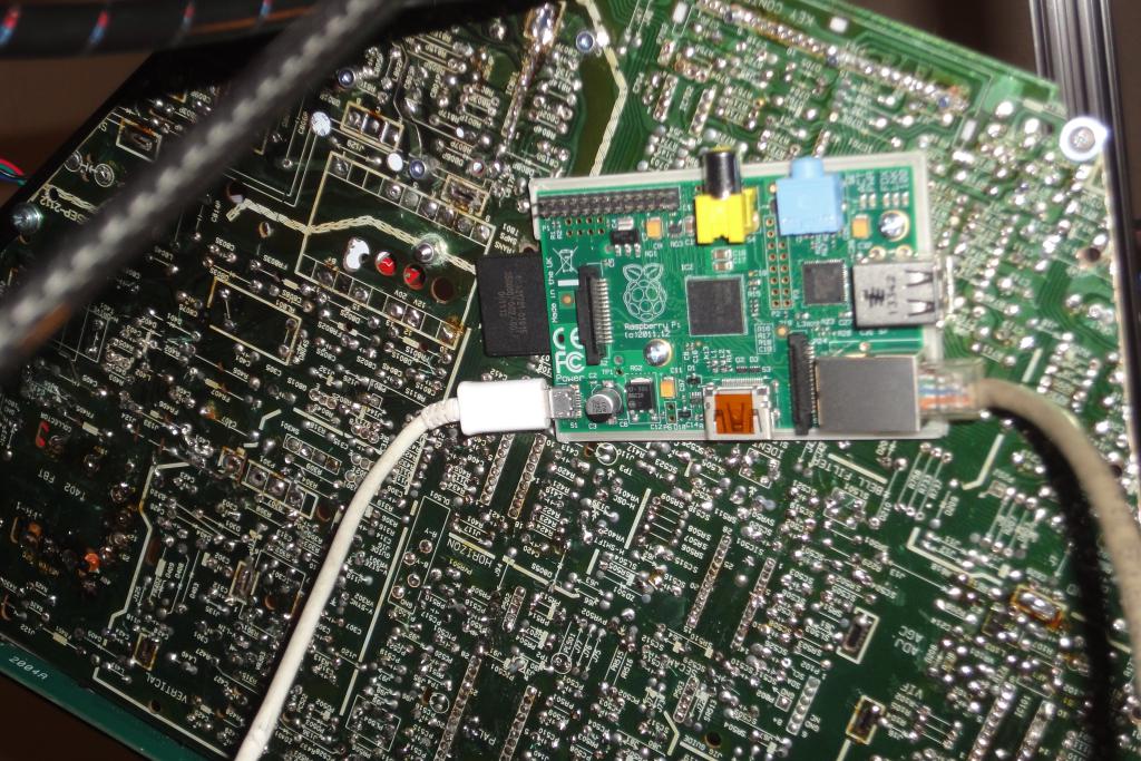 Raspi mount |
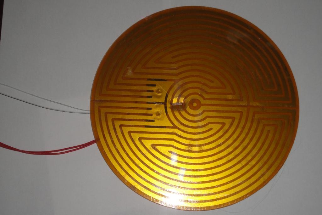
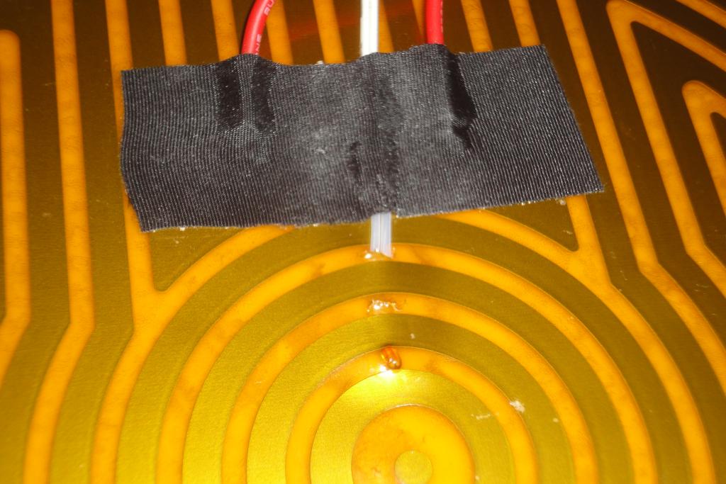
A self-adhesive heater was attached to the printer bed. The cables were extended by about 20-25 cm. The thermistor cable was also extended and a connector was attached to its end.
The thermistor was attached between the heater and the bed. A hole was pierced in the kapton sheet, the thermistor slid through, and the sheet itself used to hold the thermistor in place. This configuration should be less influenced with airflow around the bottom of the bed and better reflect the temperature of the glass sheet.
The hot bed required replacement of the laptop-grade power supply with an ATX power supply.
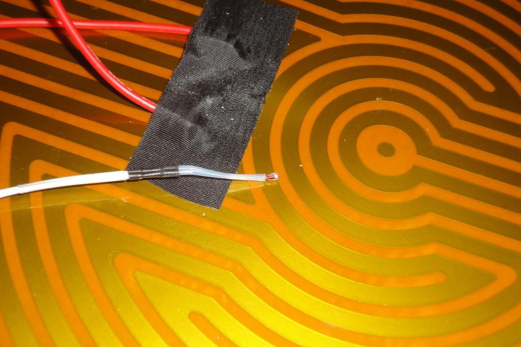 Hot bed and thermistor | 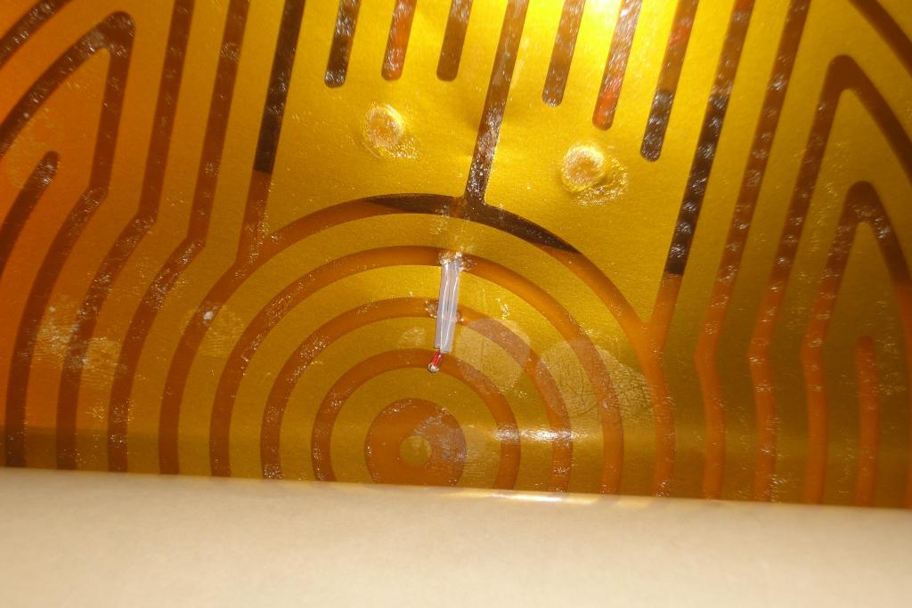 Hot bed and thermistor | 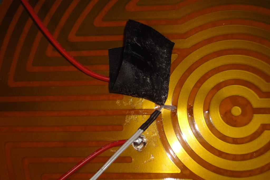 Hot bed and thermistor | 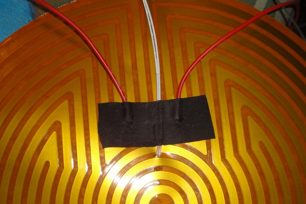 Hot bed and thermistor |
 Hot bed glued to glass | 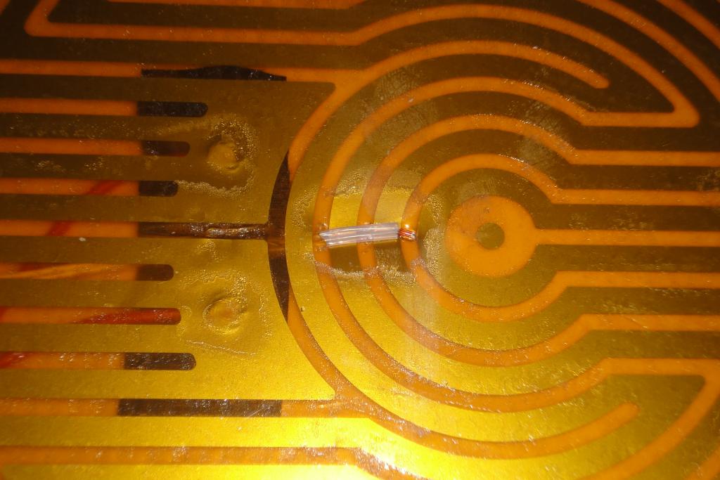 Hot bed glued to glass | 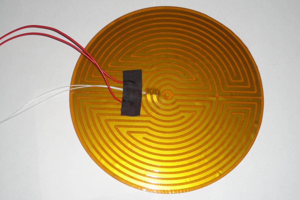 Hot bed glued to glass | 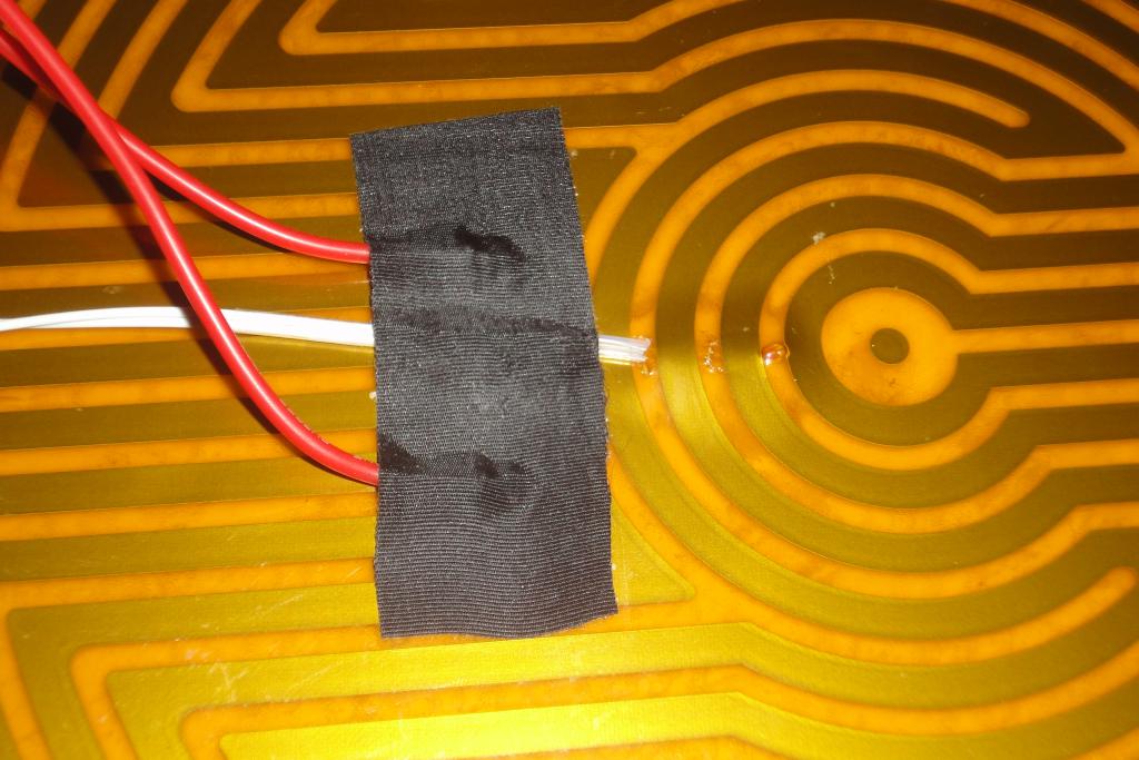 Hot bed glued to glass |
 Hot bed glued to glass | 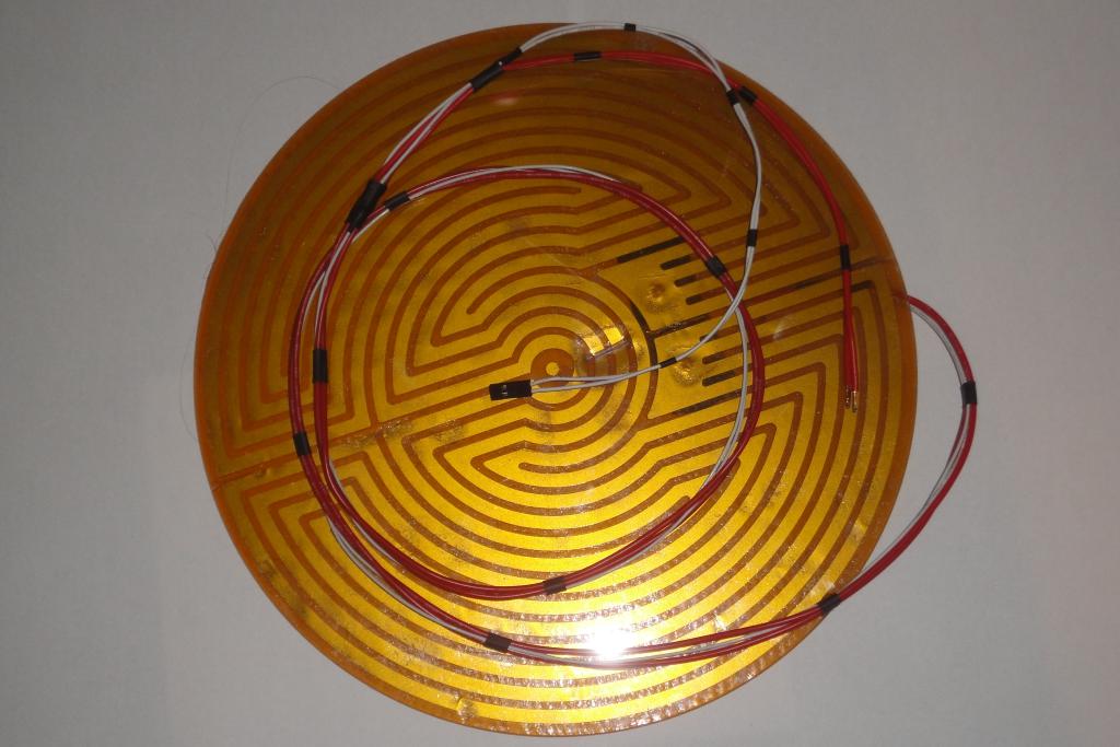 Hot bed glued to glass |
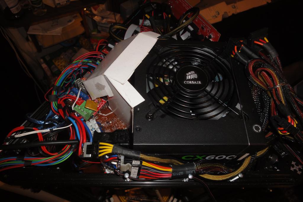
A 600-watt ATX power supply was chosen on the basis of being on hand; otherwise a 400-watt would be sufficient. The power supply was placed to the top frame, fixed to the mount plate with one L-bracket and a U-shaped length of wire.
 Top frame assembly | 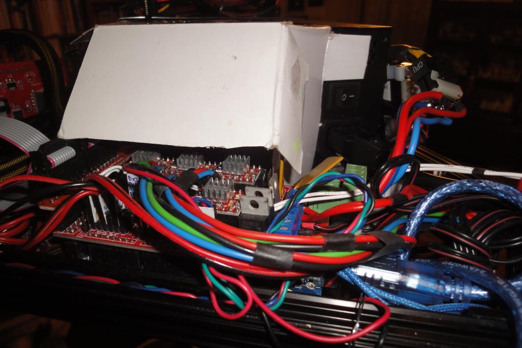 Top frame assembly | 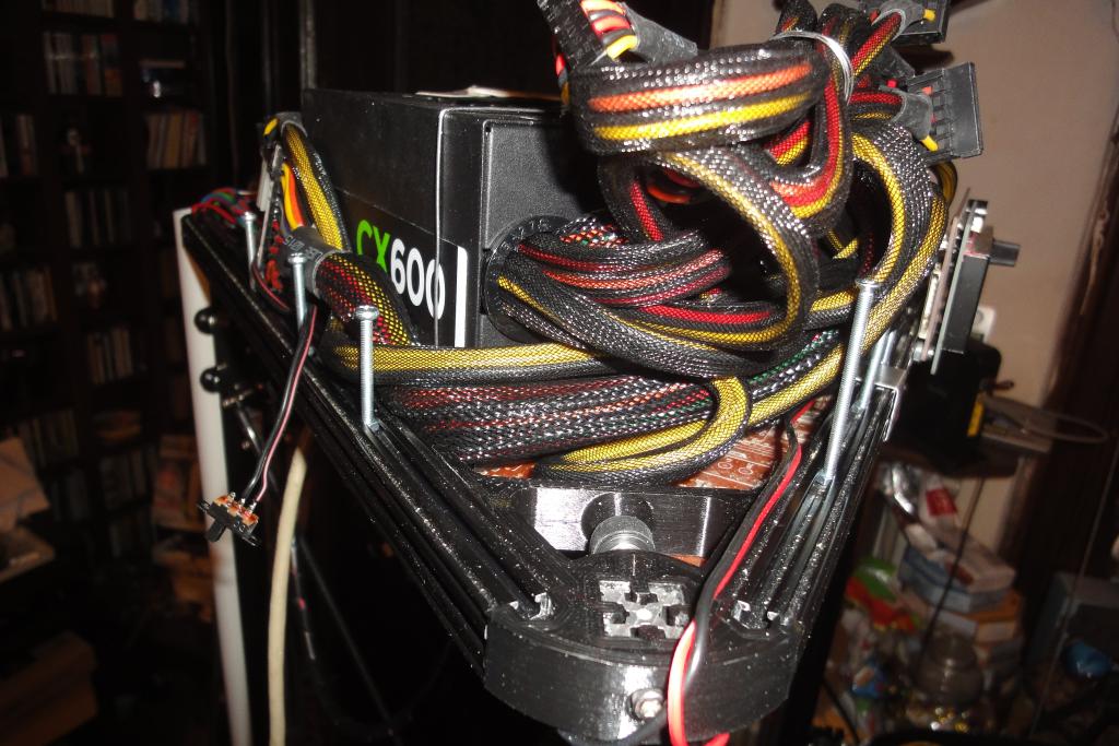 Top frame assembly | 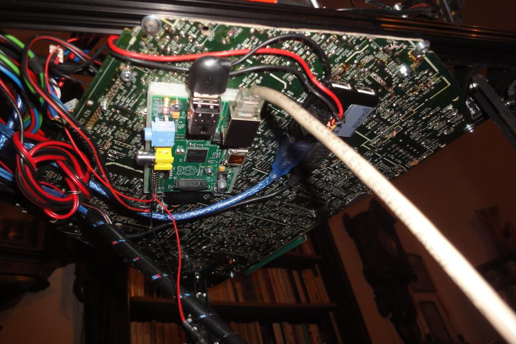 Top frame assembly, bottom side |
One of the GPIOs of the host computer board was connecte to the base of a NPN transistor. The transistor was connected between the power-control line of the ATX PSU connector (the green wire) and ground. High level on the GPIO now powers up the ATX PSU.
The controller and the webcam aren't needed when the printer is depowered. The host computer would however feed them via the USB. A USB hub was therefore used; its USB power wire was cut and attached instead to the non-standby 5V rail of the ATX PSU. This automatically powers and depowers the controller and all the auxiliary equipment when the printer is powered on or off.
A switch is added to allow selection between the standby and non-standby power, to facilitate development without having to power the whole machine.
For more details, see mod_USBhubPowered .
.
The location of the computer and power supply on the top of the machine has a disadvantage; the cables are usually routed from bottom. Cables then have to go along the sides of the machine and are getting in the way.
The vertical cable tube was leveraged for getting the network and power from top to the bottom.
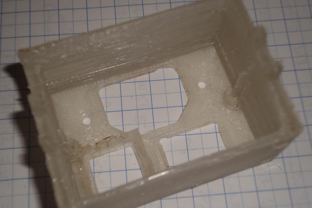
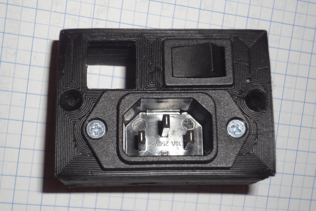
A box was designed, using an OpenSCAD library for panel components. It was printed. Turned out that the printer made the holes a notch smaller, so a little Dremel mill hand-postprocessing was needed to be done. Afterwards, the box was spray-painted black, and populated with the socket and switch.
A short mains and Ethernet "patch cables" were attached to the power supply and computer and led down to the socket box at the base of the printer.
For Ethernet, the Keystone patch panel socket was used. A skirt was printed to hold its face in place. The box was designed around its height, so when attached the socket is held from the back by the mounting rail of the printer.
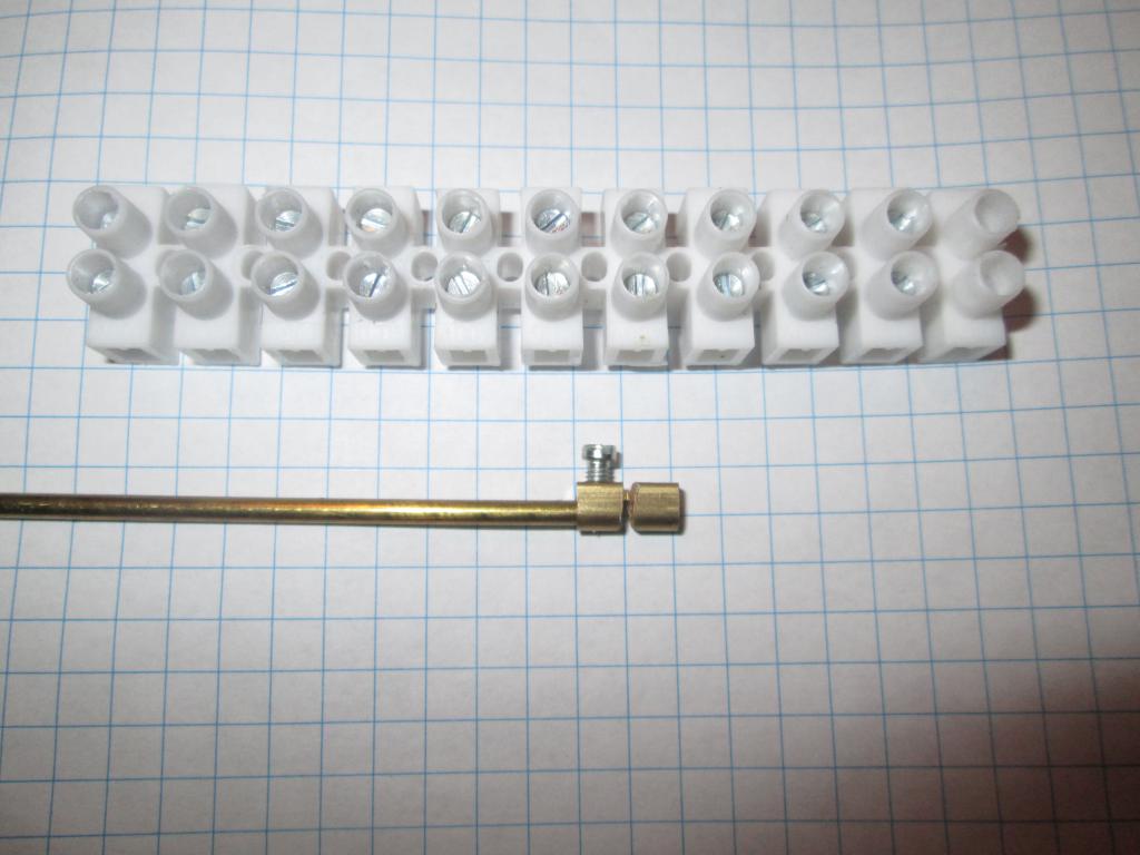
The mains cable was attached using screw clamps. Originally the clamps were to be soldered individually to the socket and switch, but then it was found that the whole clamp assembly can fit in. Fast-on contacts could also be used but they were not on hand.
The box is printed from PLA, as a temporary solution. A flame-retardant ABS will be used in next iteration.
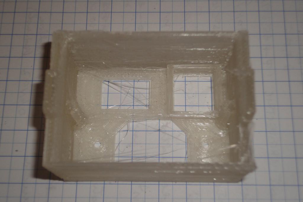 Power box, as printed | 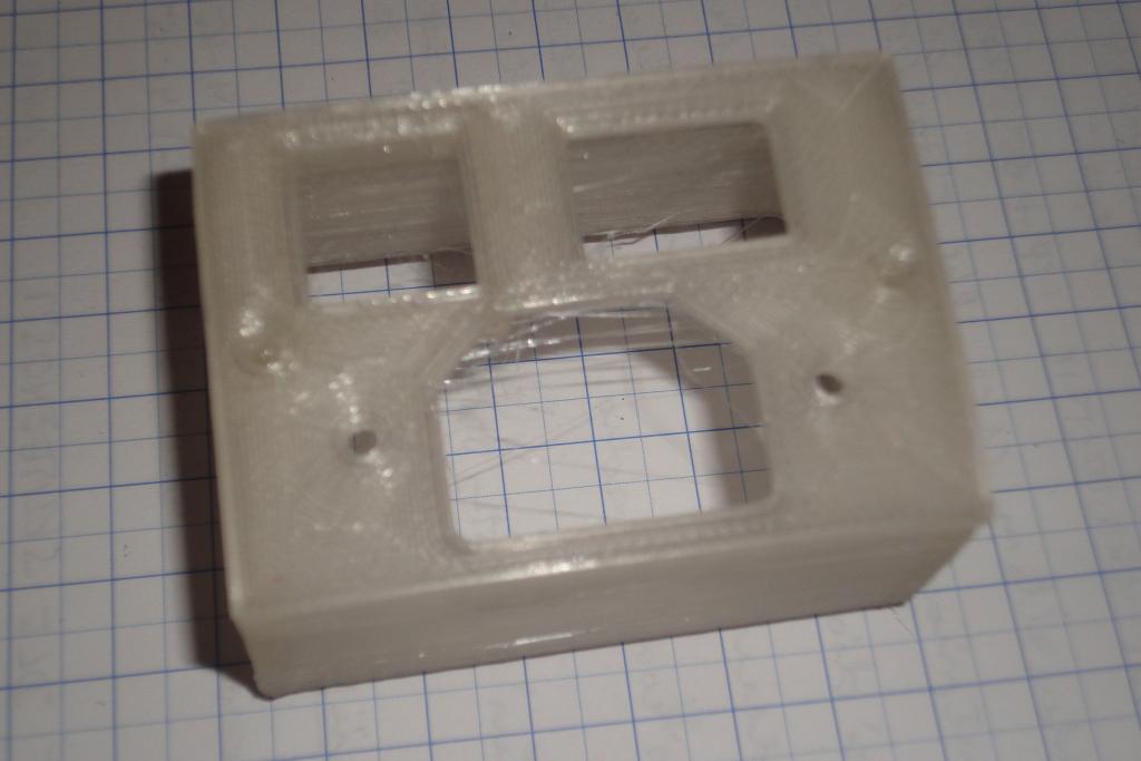 Power box, as printed | 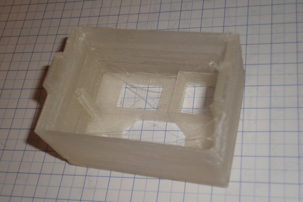 Power box, as printed | 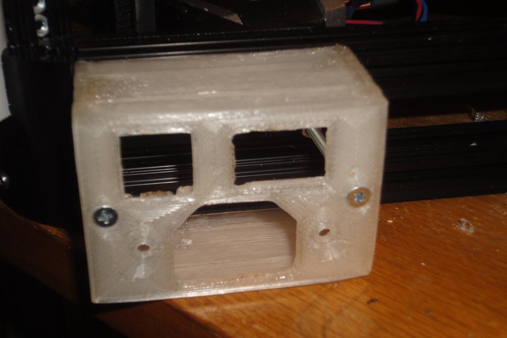 Power box, attachment |
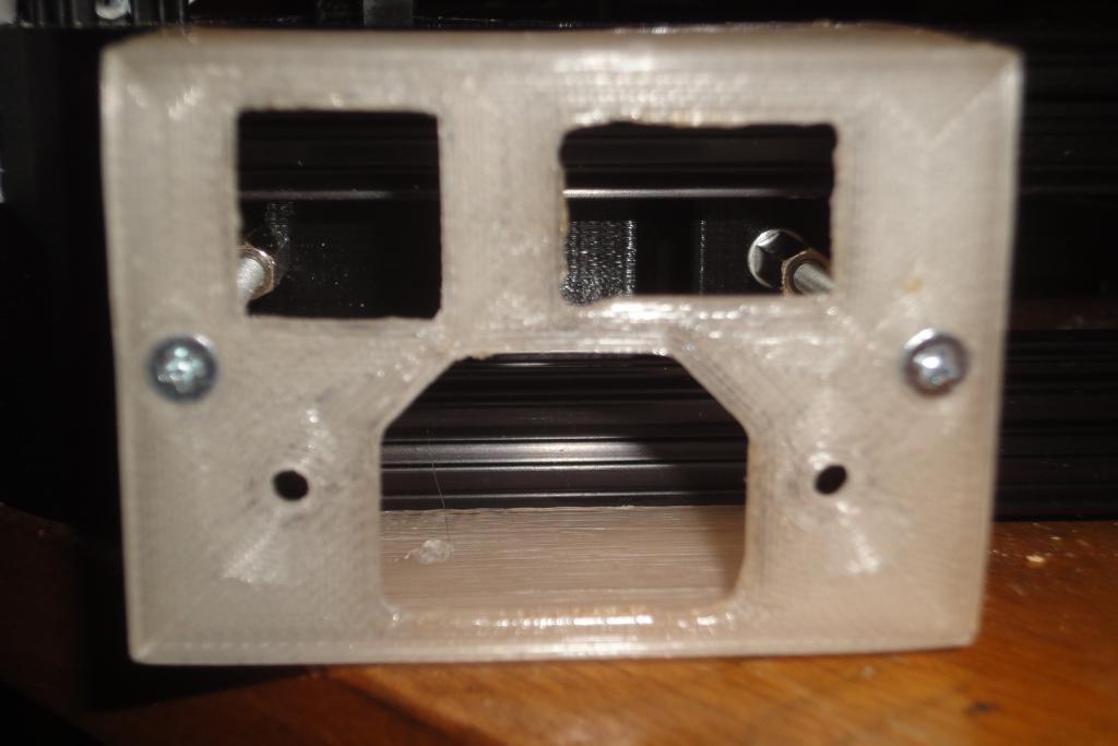 Power box, attachment | 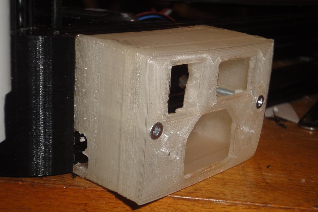 Power box, attachment | 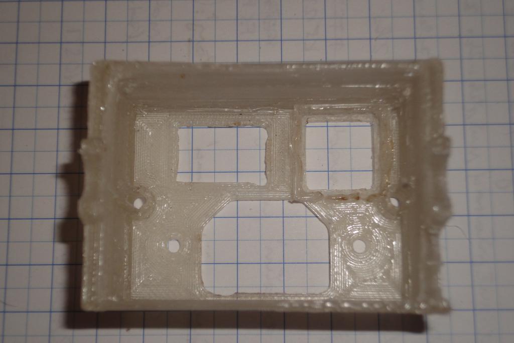 Power box, postprocessed | 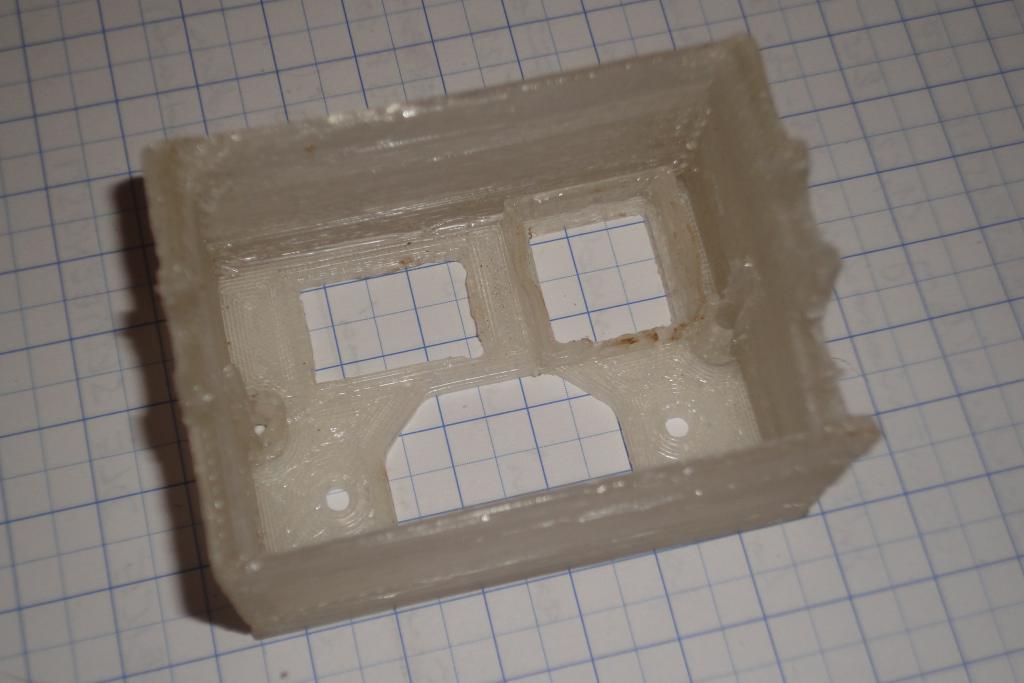 Power box, postprocessed |
 Power box, postprocessed | 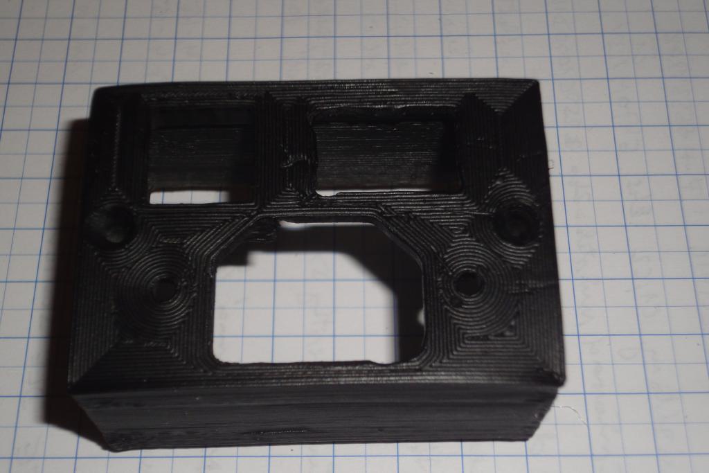 Power box, painted | 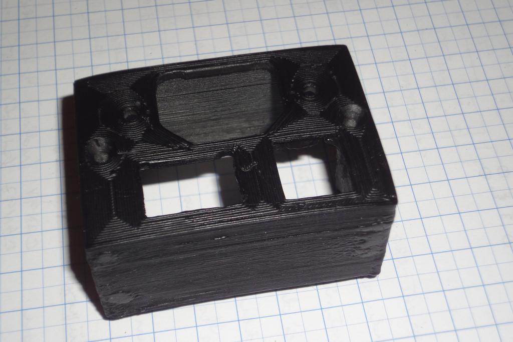 Power box, painted | 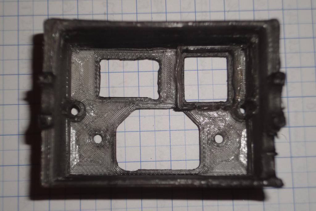 Power box, painted |
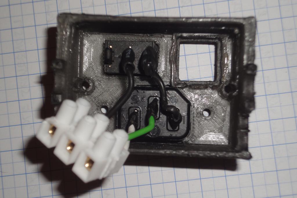 Power box, wiring | 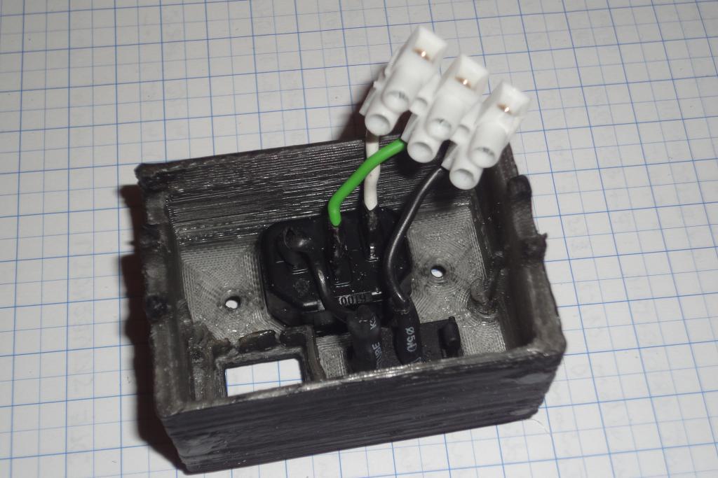 Power box, wiring | 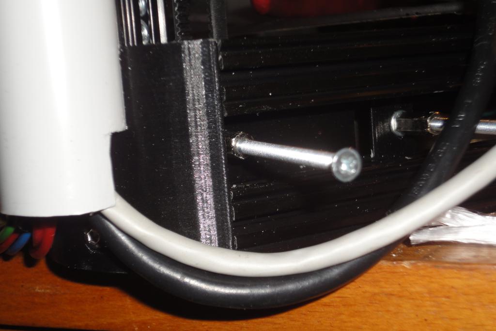 Power box, cables | 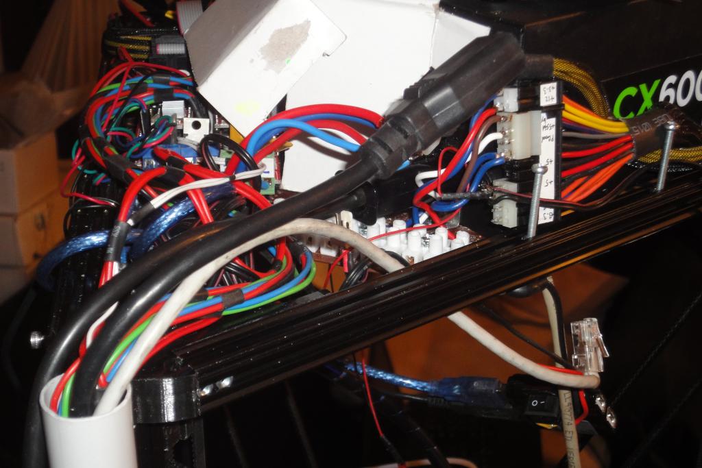 Power box, top cables |
 Power box, switch and socket | 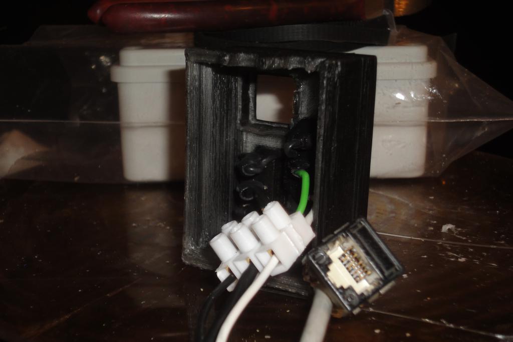 Power box, wired up | 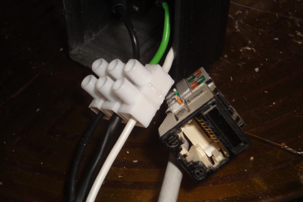 Power box, wired up | 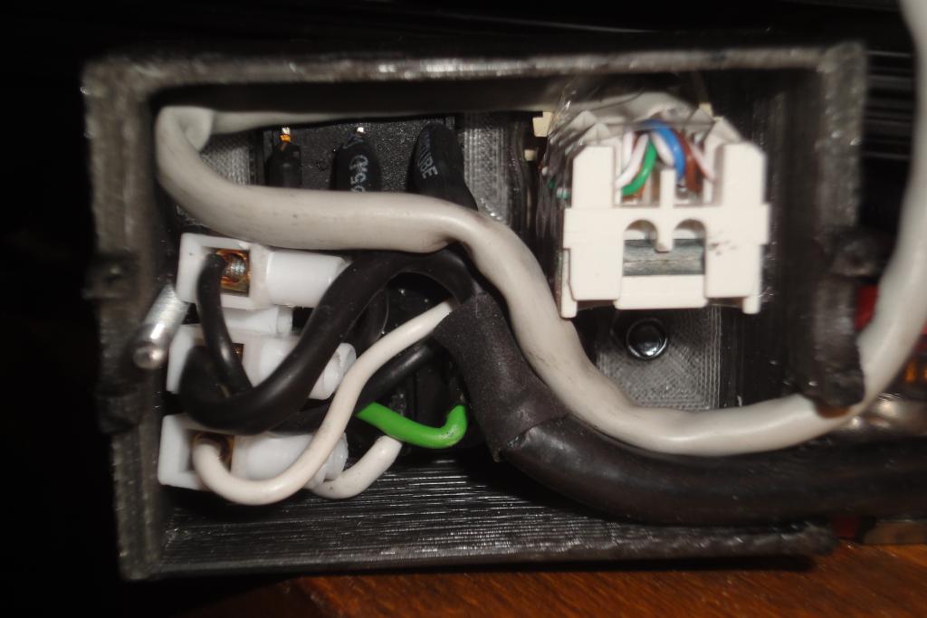 Power box, wired up |
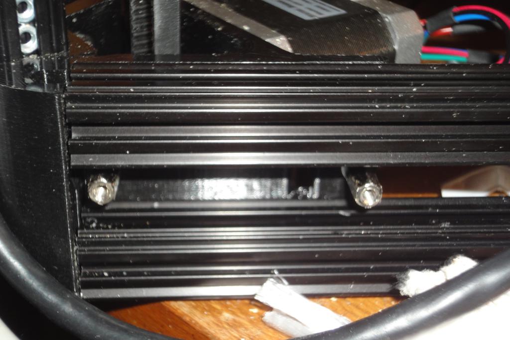 Power box, attachmet points | 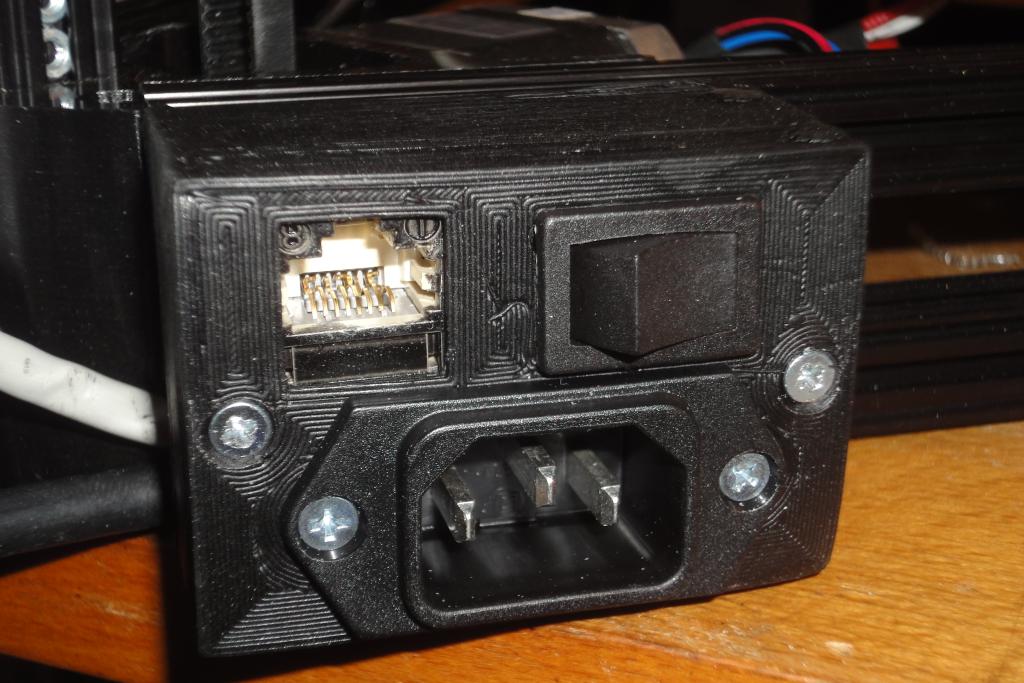 Power box, installed | 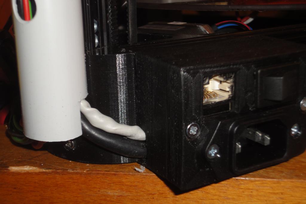 Power box, installed | 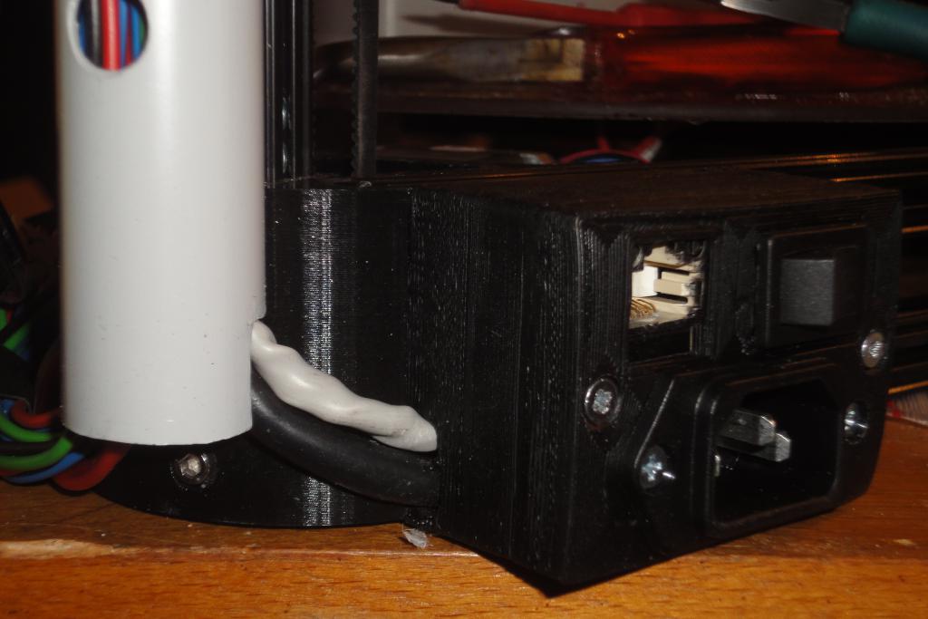 Power box, installed |
For more details, see 3d_KosselXLHeadFanMount.
