In workshop use, the camera has a power supply always nearby. In contrast, its batteries
often get depleted in the worst possible timing. The camera has a 9V power connector, with a
connector that is probably a 4.75x1.7 mm barrel jack (EIAJ-03 standard).
The documentation suggests the Casio AD-C100 power supply, which is equipped with this connector
and has specified output of 8.4V/0.56A.
(EIAJ-03 standard).
The documentation suggests the Casio AD-C100 power supply, which is equipped with this connector
and has specified output of 8.4V/0.56A.
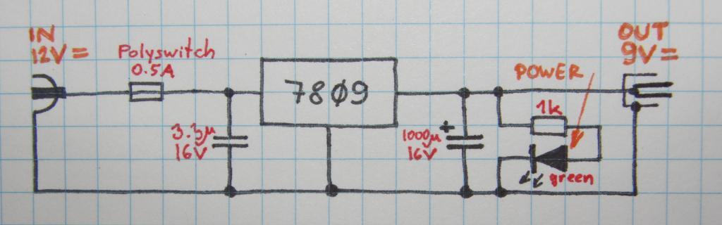
Of course, the power supply that's always available is the 12V model with 5.5x2.1 mm jack. A voltage stabilizer was therefore desired.
There is always a choice between a linear and a switching regulator. The linear one was chosen as there is only fairly low voltage to drop and there's not much of current to deal with as well, so there's not much of waste power and heating. A 7809 stabilizer was chosen on the basis of cost and availability.
A 13mm wide piece of a 40x20 aluminium hollow profile was cut and holes were drilled for the stabilizer screw and power connectors. There was also a hole drilled opposite to the stabilizer screw, with dual use for access to the stabilizer and for the LED.
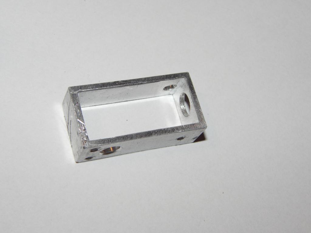 Heatsink and mounting block | 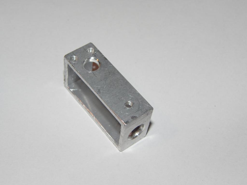 Heatsink and mounting block | 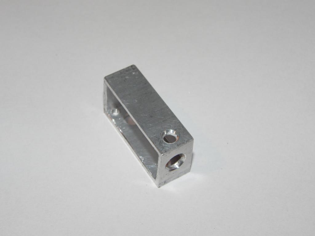 Heatsink and mounting block |
The stabilizer, with the wing smeared with thermal paste, was screwed onto the heatsink.
A 4 mm green LED was then set into the hole. The 5.5/2.1 mm power connector was then
set into the side hole.
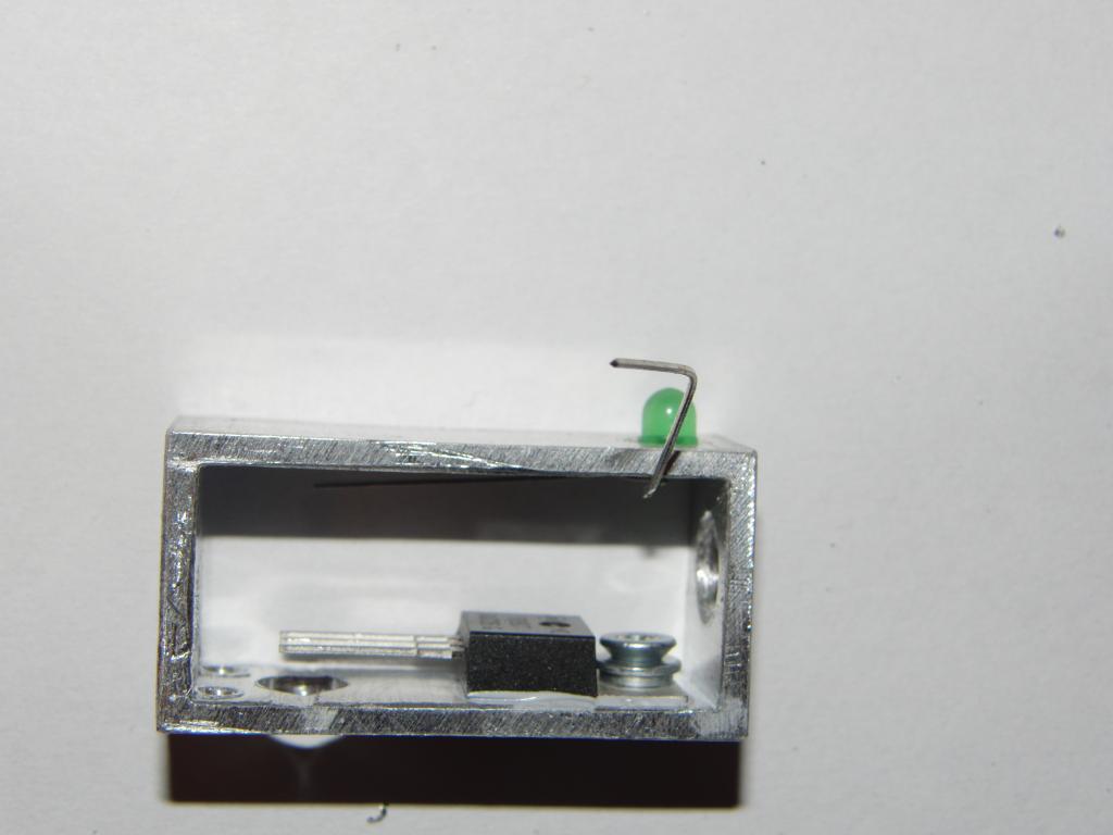 LED and stabilizer | 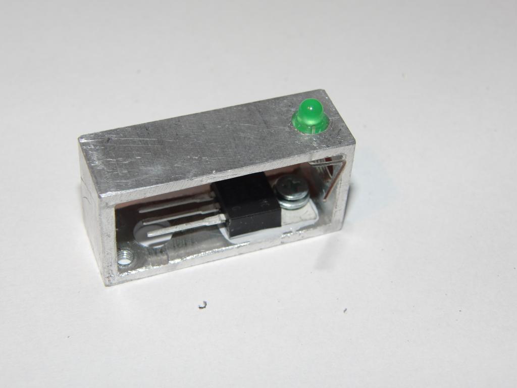 LED and stabilizer | 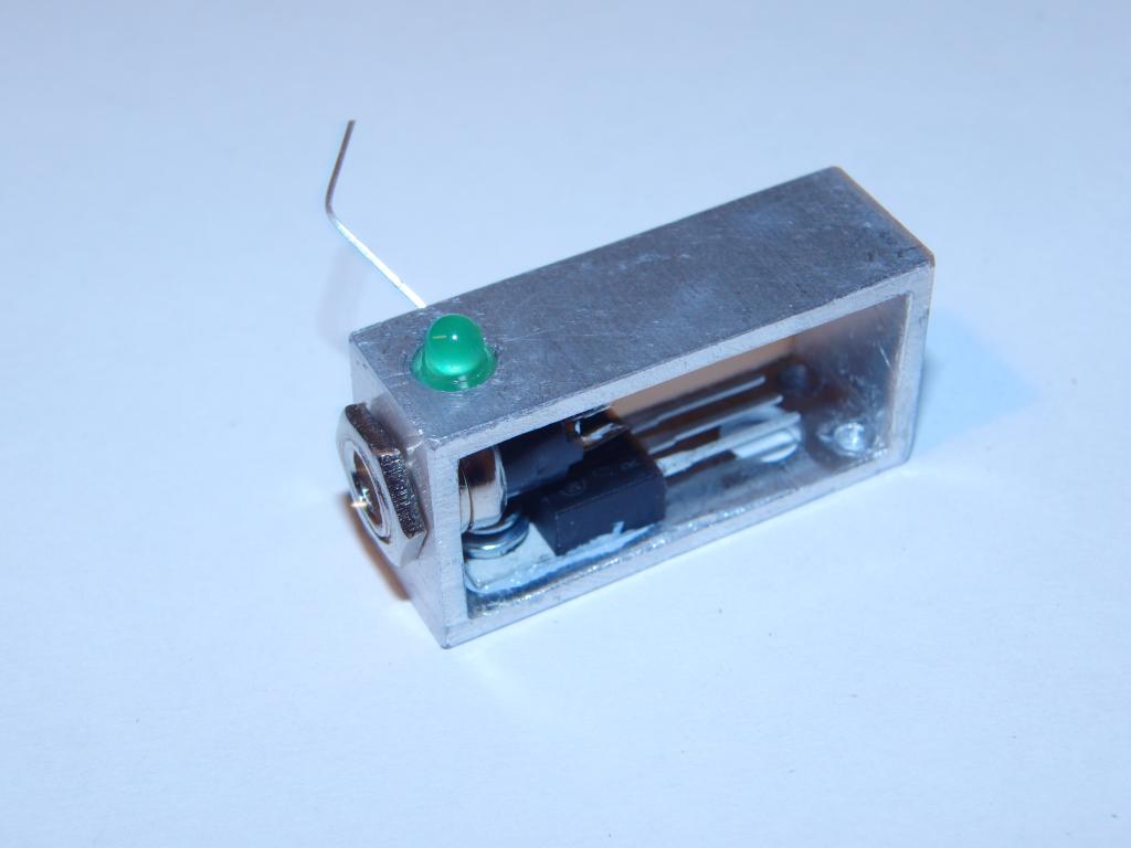 LED, stabilizer, power connector | 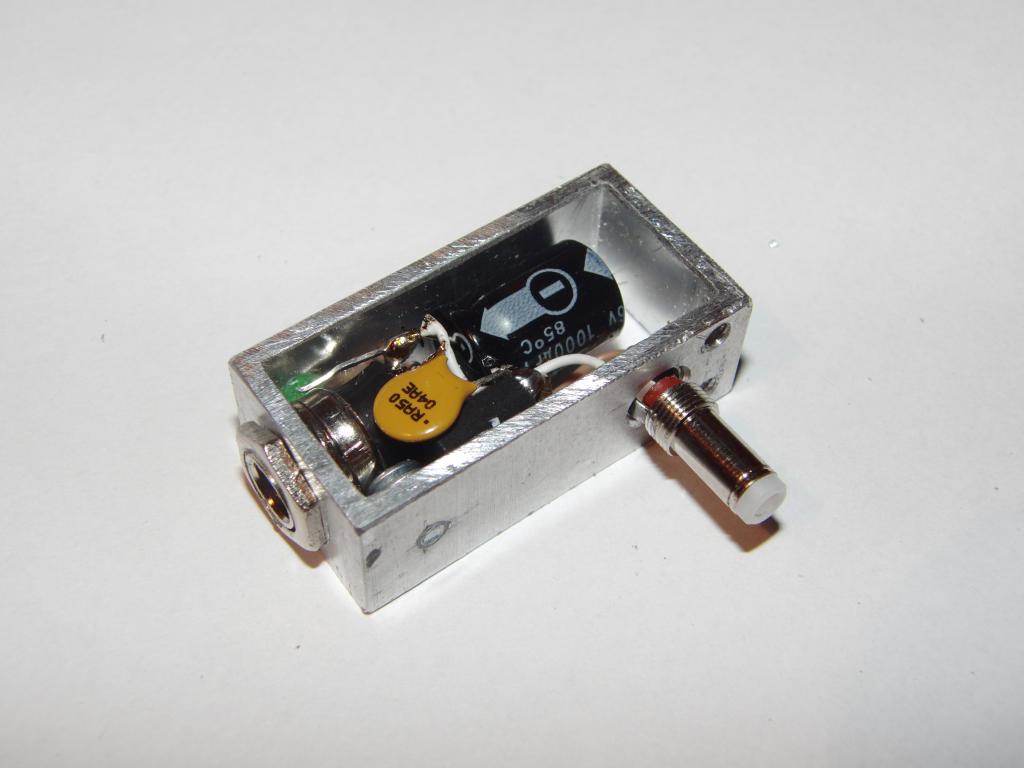 LED, stabilizer, power connectors, fuse |
 LED, stabilizer, power connectors, fuse |
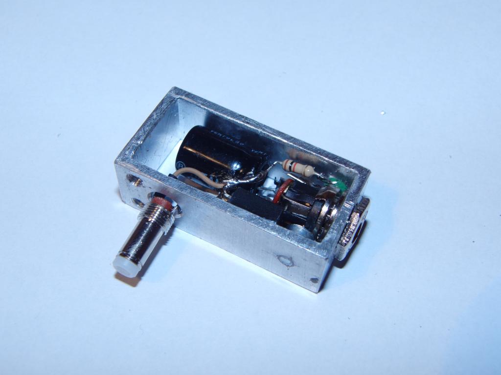
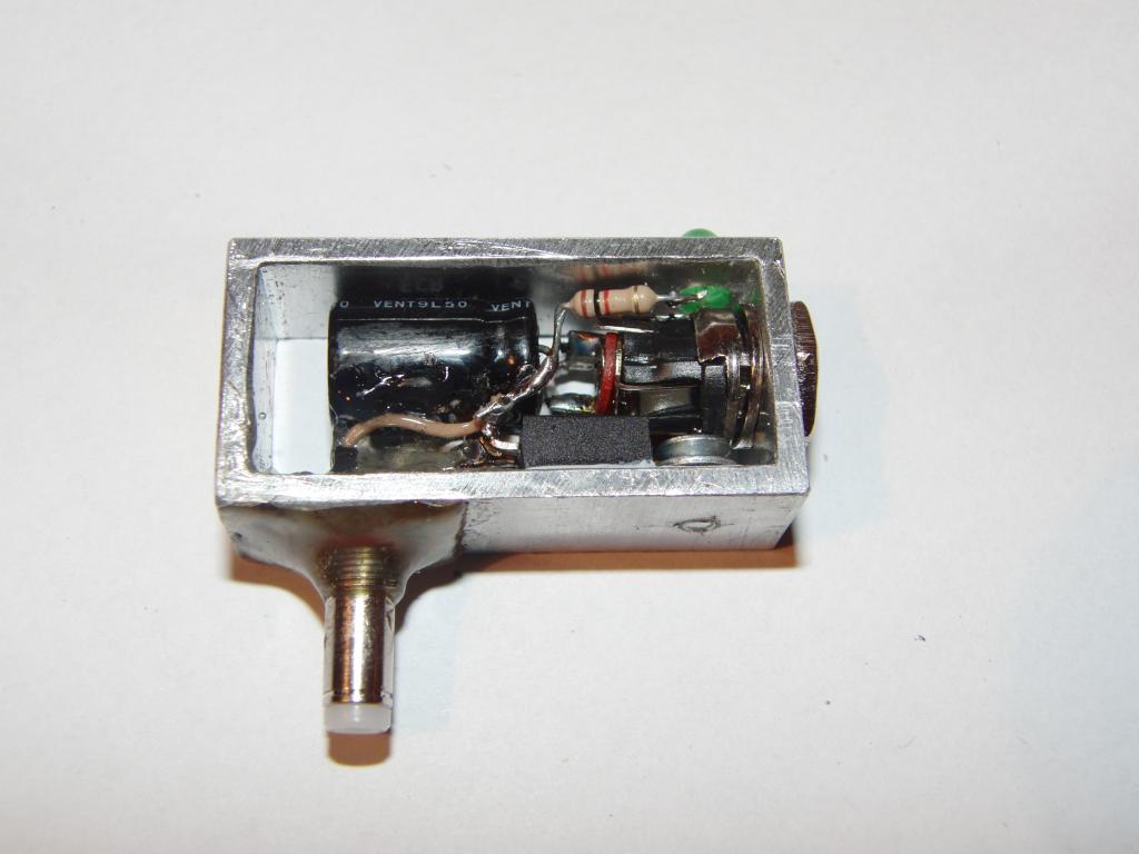
The Polyswitch fuse (to avoid surprises), the electrolytic output capacitor, and the
resistor for the LED were then connected. A ceramic SMD capacitor was soldered onto the
stabilizer between the input pin and ground (because it was small, cheap and on hand; electrolytic
one would do the same job).
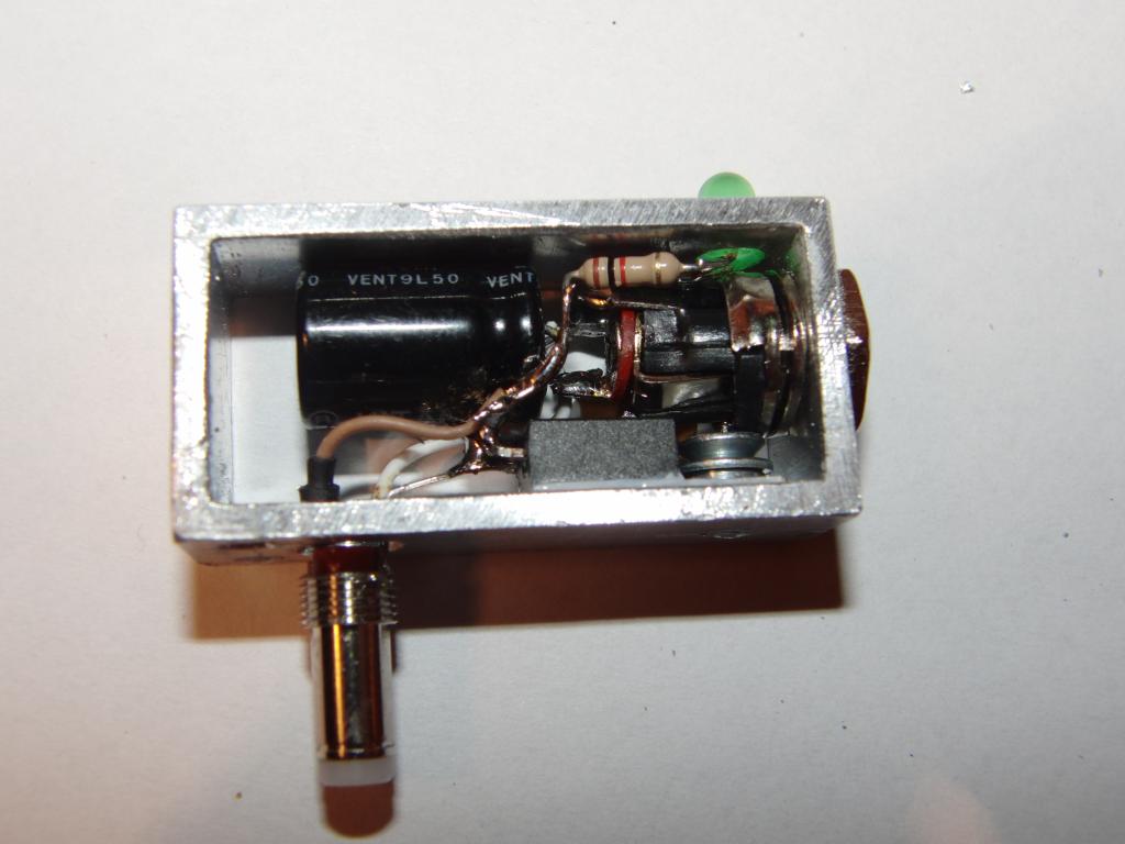 Finished circuit, one side | 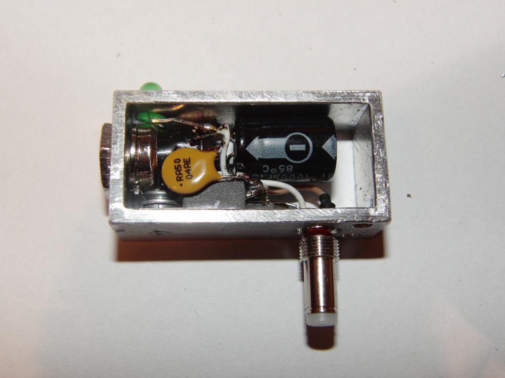 Finished circuit, other side |
The camera-side connector, a 4 mm barrel type, was then secured to the housing with hot-melt adhesive, using butane torch to preheat the housing to be well-wetted by the glue.
 Camera connector mount | 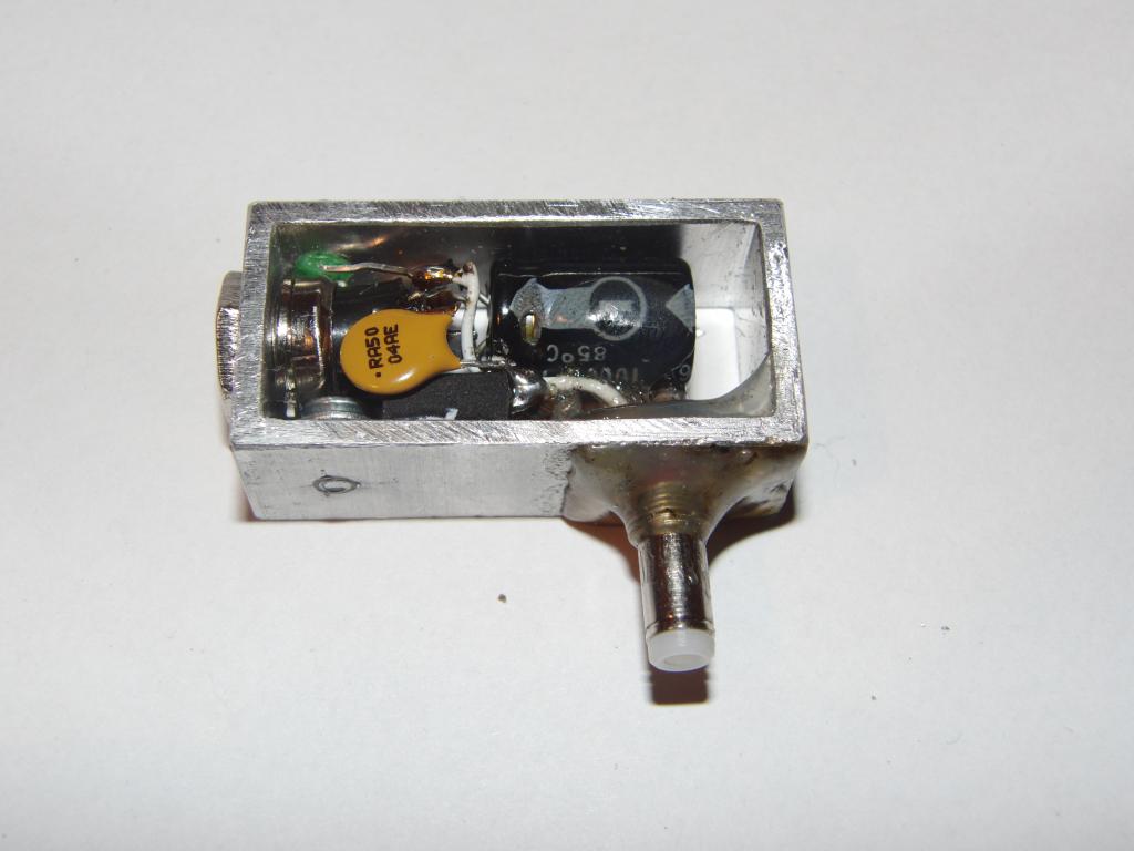 Camera connector mount | 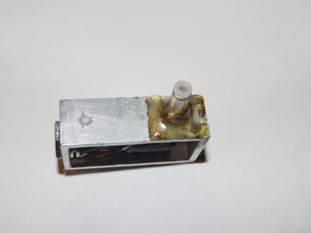 Camera connector mount |
The circuit was then tested and found to be operational.
The exposed sides of the casing were then covered with aluminium metal sheets. Rectangles 40x20 mm were cut from a roofing sheet. Hot-melt adhesive was deposited to the side of the housing. The cover sheet was placed over it and heated carefully with a butane torch until the glue melted again and well-wetted both surfaces. The sheet was then pushed down using a piece of wood, and precisely maneuvered into position. The same was repeated with the other side. The edges were then filed down to precisely conform to the rectangle.
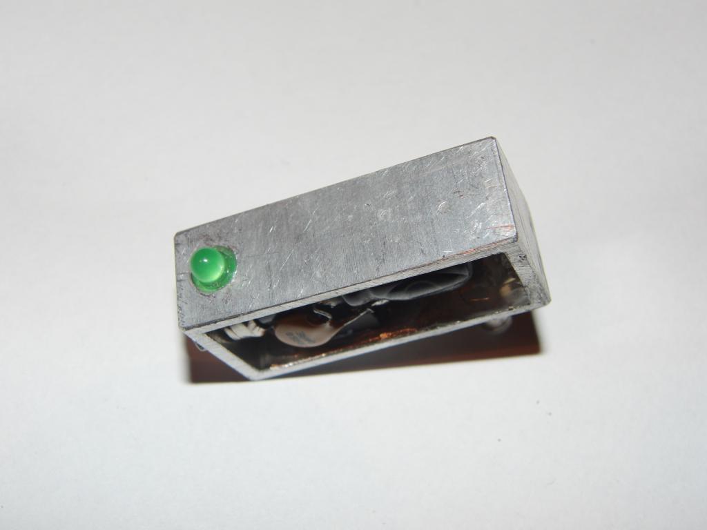 Top side view | 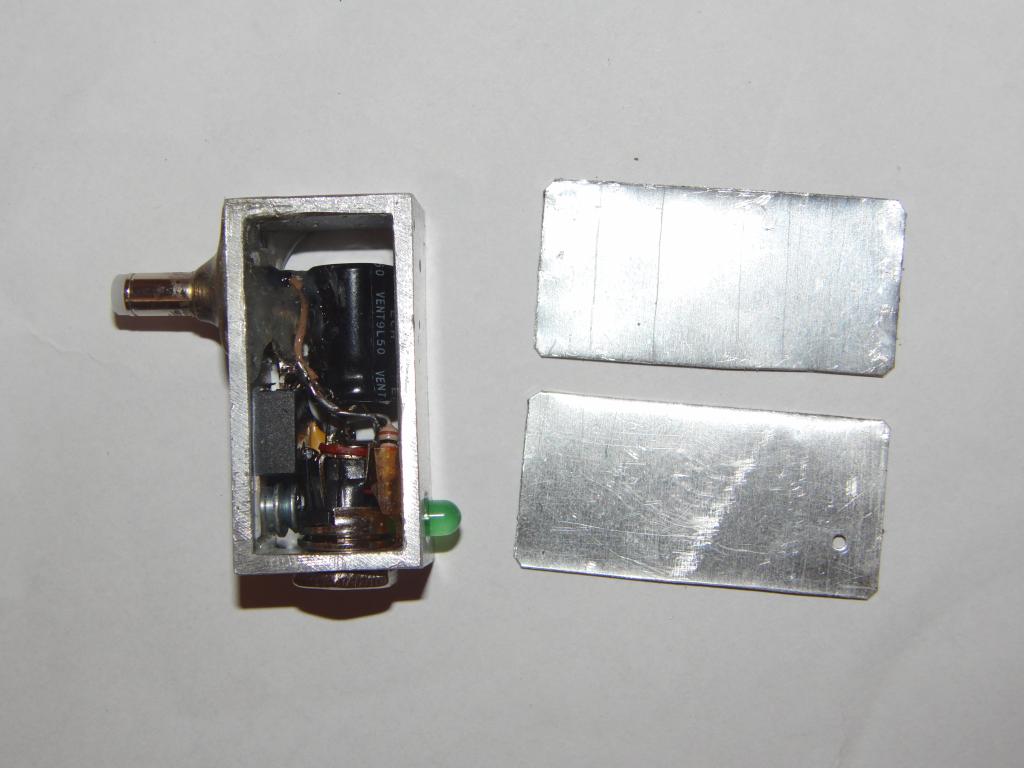 Side walls |  Hot-melt adhesive |  Wall glued in place |
 Wall glued in place |
The field tests shown that the assumption that the compact power supply with the camera connector integrated to its housing will have superior performance turned out to be deeply flawed. The 12V-side cable tended to pull on the housing and the connector held in the camera too poorly to provide sufficient mechanical integrity and tended to slip out early and often. There was also the concern of mechanical overloading of the circuitboard inside the camera. The device therefore had to be modified.
 Wall unglued | 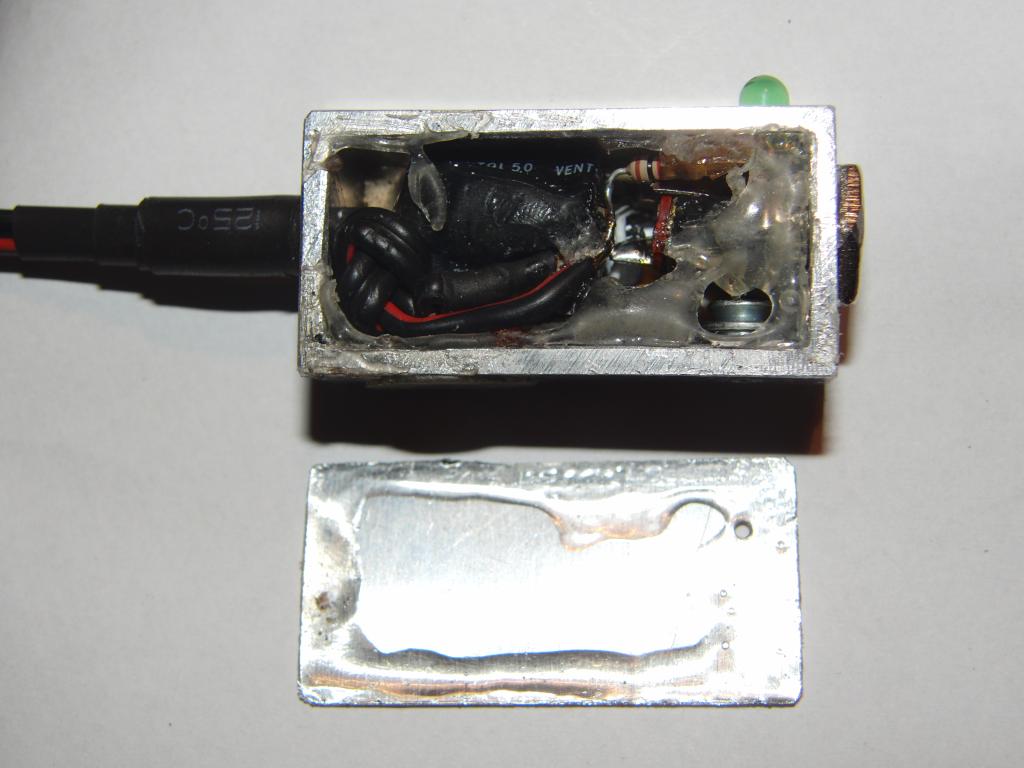 Wall unglued |
One side of the housing was heated with the torch and the hot-glue melted; the wall was then removed. The glue holding the camera connector in its mounting hole was heated and the connector was removed from its site and cut away from the wires.
A hole for the cable outlet was drilled in the box. A length of a two-wire cable was cut. A knot was made near one end and the cable was pulled through the freshly drilled hole. The wires were connected to the positive and negative outputs of the circuit. Heat-shrink tubes were placed on the cable and shrunk, forming a strain relief. To boost its performance in the closest vicinity of the metal housing, where the strains are strongest, a layer of hot-melt adhesive was deposited around the cable.
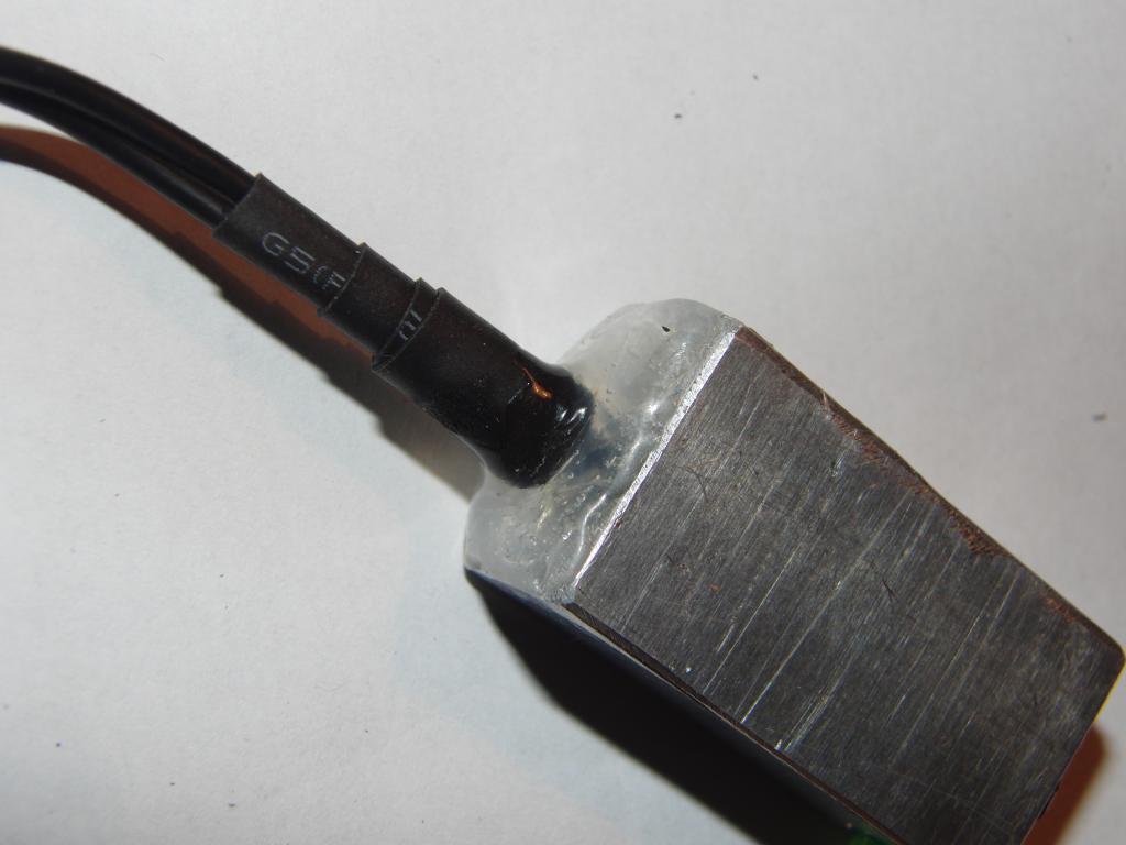 Box-side cable strain relief |
A number of heat-shrink tubes of selected lengths and diameters were placed on the cable before the connector was attached; it was experimentally proven that it is a much easier way than to have to force the connector through a tube narrower than its outer diameter. The connector was attached to the free end of the cable. The tubes were sequentially pulled over the connector's contacts and part of its body and shrunk in place. At the end, the strain relief part was heated to softening temperature, bent into a 90-degree angle, and then held until it cooled; this fixed the angled strain relief in place.
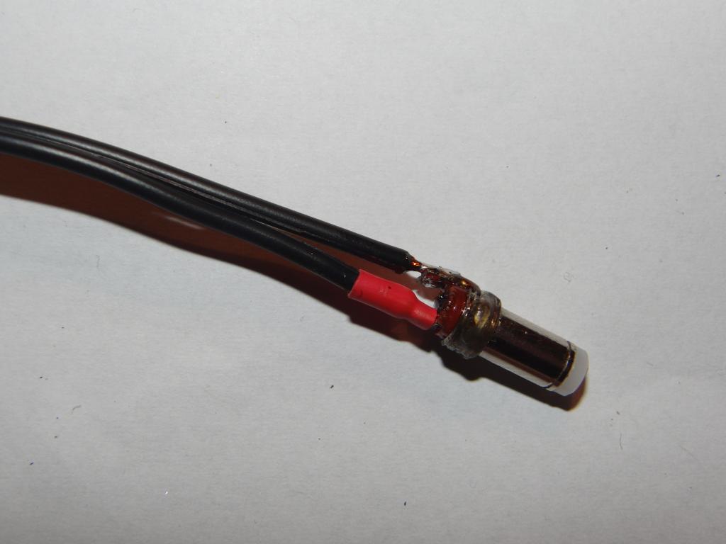 Connector detail | 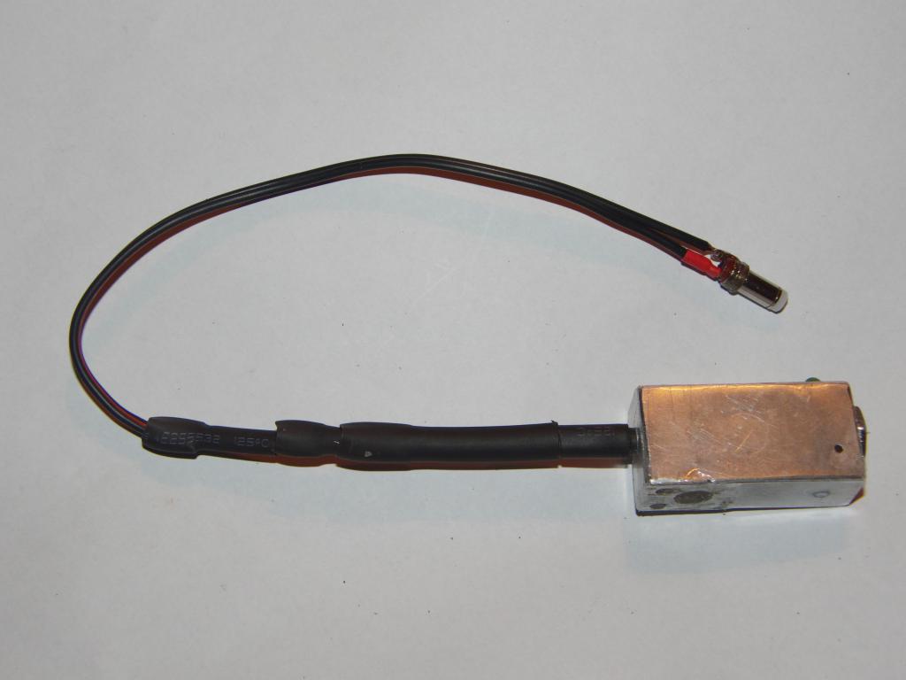 Cable with connector | 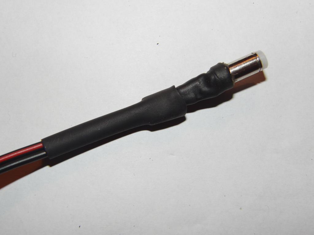 Connector with heatshrink layer | 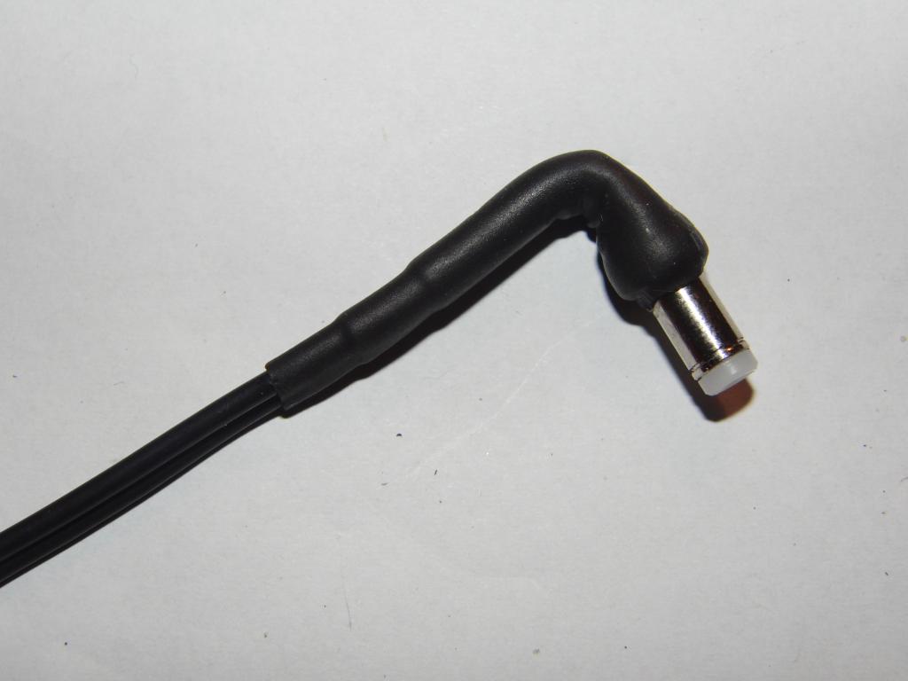 Angled heatshrink housing and strain relief |
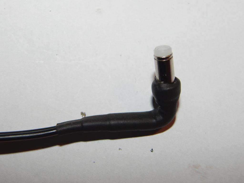 Detail of the connector housing | 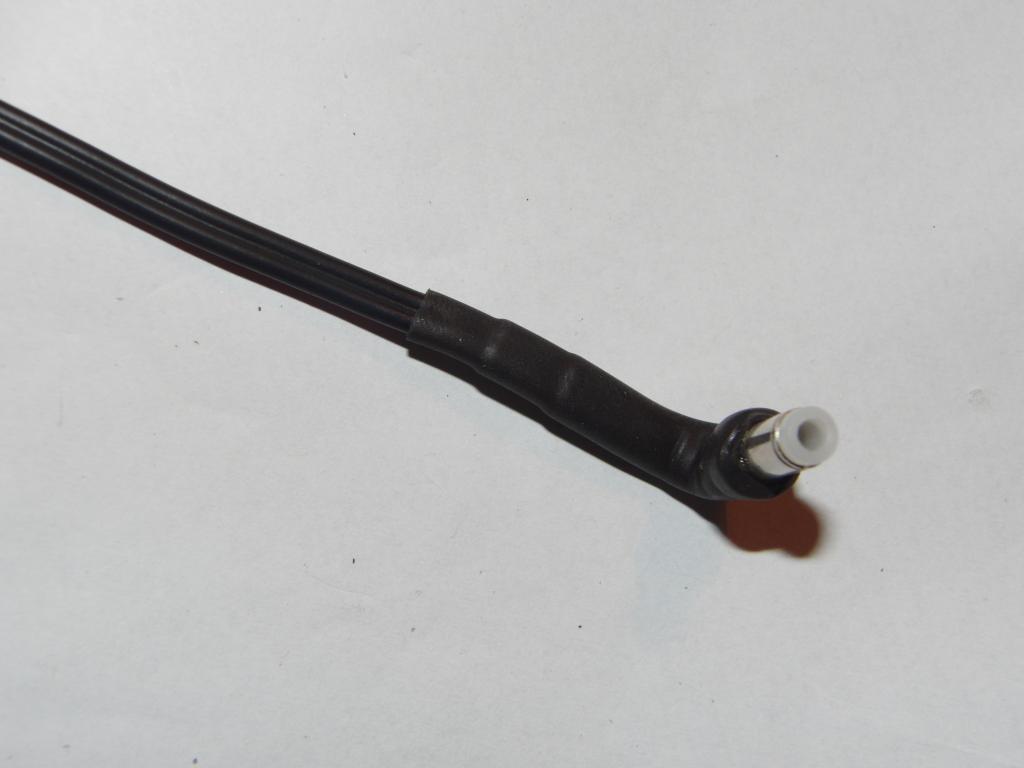 Detail of the connector housing | 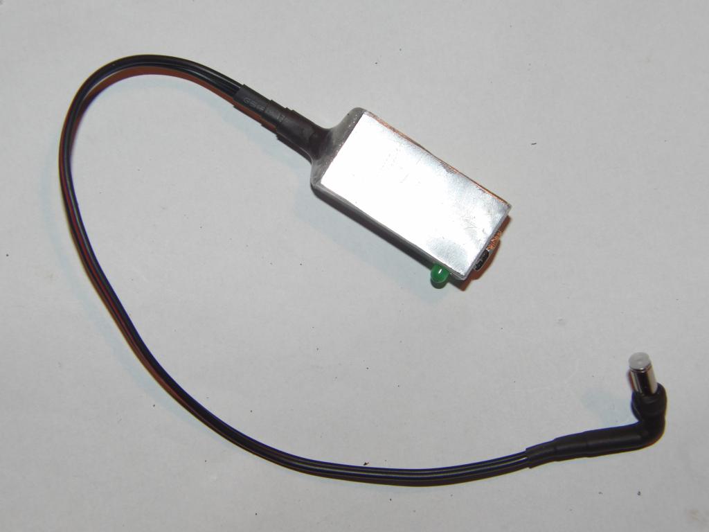 Box with cable |
The assembly was then attached to the camera carrying strap. The cable now exerts only minimal
force on the connector and the carrying strap prevents it from being pulled out. The camera can now be
powered easily from a 12-volt wall wart or an ATX power supply.