Because capacitor plague is one of the most common
reasons for electronics failure. Some brands of capacitors
is one of the most common
reasons for electronics failure. Some brands of capacitors are better than others;
some tend to be good (and typically expensive), some tend to vary with time, others, e.g. "CrapXon" (aka CapXon,
a common failure cause of Acer-brand flat panel monitors), maintain consistently bad reputation.
are better than others;
some tend to be good (and typically expensive), some tend to vary with time, others, e.g. "CrapXon" (aka CapXon,
a common failure cause of Acer-brand flat panel monitors), maintain consistently bad reputation.
As the capacitor ages, its ESR increases;
the capacitor, especially when subjected to high ripple currents, heats from inside and the process self-accelerates.
The capacitor often bulges, vents electrolyte, or even explodes; but sometimes it just sits there and does not work much
anymore.
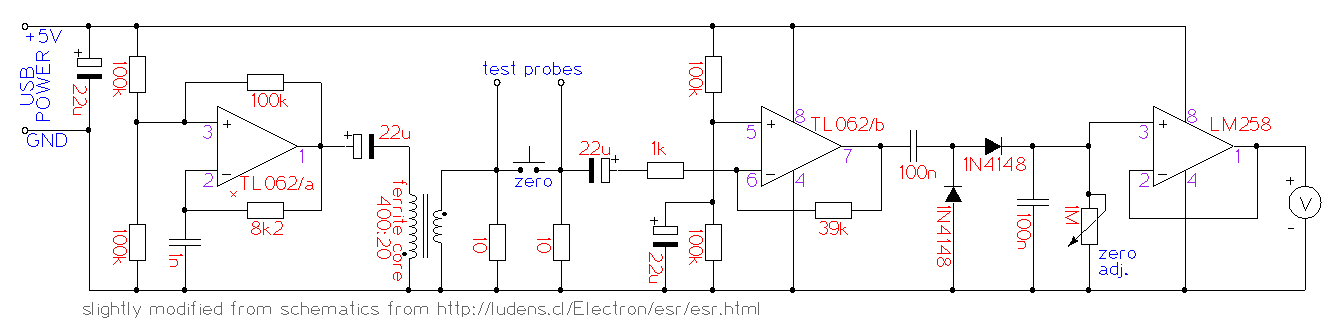
A way to test ESR of the capacitor is subjecting it to small-amplitude AC voltage and measuring the current through
the cap, like it is done with DC when measuring resistance. This device uses a small enough amplitude (200 mV, lower than the
opening voltage of most semiconductor junctions), at about 60 kHz, to allow its use in-circuit, on the capacitors soldered on the boards.
More discussion of the function is on this page .
.
The unit is an almost-straightforward copy of the ESR meter by Manfred from Chile
(who also has other interesting and useful articles on his website about e.g. transformers),
with several minor modifications. I use USB for source of fairly stable 5V, in addition to the stabilizer (first omitting it,
later including it after finding that dual power capability is worth the cost of a 78L05). I also used a much cheaper VU meter as a voltmeter,
with correspondingly lousy parameters; this necessitated the addition of the LM258 chip as a buffer for the meter (in the original
circuit the needle barely moved), and a change in connection of the zero-adjusting trimpot.
Later a power connector for a 12V power supply was added, with a 78L05 chip to supply the stabilized 5V for the internal electronics.
The transformer used inside is wound on a tiny (~6mm outer diameter) ferrite toroid, using very thin wire so the required 400 turns can fit on the coil. To save work, the wire for the 400-turns side was folded to half, half, and another half, yielding a 8-strand "cable", which required just 50 turns, followed by 7 solder junctions of the ends (the cost of not having to make 350 more turns); these are somewhat visible under the layers of hot glue on the detail of the electronics and look like a certain kind of cute punk hairstyle on the coil.
For user comfort, a button was added that shorts the leads and sets the device to zero (so the zero point can be adjusted, or a small increase of ESR can be indicated by slightly moving needle when the capacitor is attached when the button is pressed).
The terminals for attaching the capacitor are banana plugs for measuring instrument leads (which add a little resistance of their own, which is noticeable but generally small). The unit also has 4+4 contacts to which leads of desoldered capacitors can be directly touched, for quick assessment of their state.
The calibration was done as described on the original page, using resistors and making marks on the dial. (Then rendering the scale in software and printing on a laser printer so it looks posh.)
Together with the Lightbulb Limiter, this tool is priceless for repair of broken power supplies in monitors and other devices.
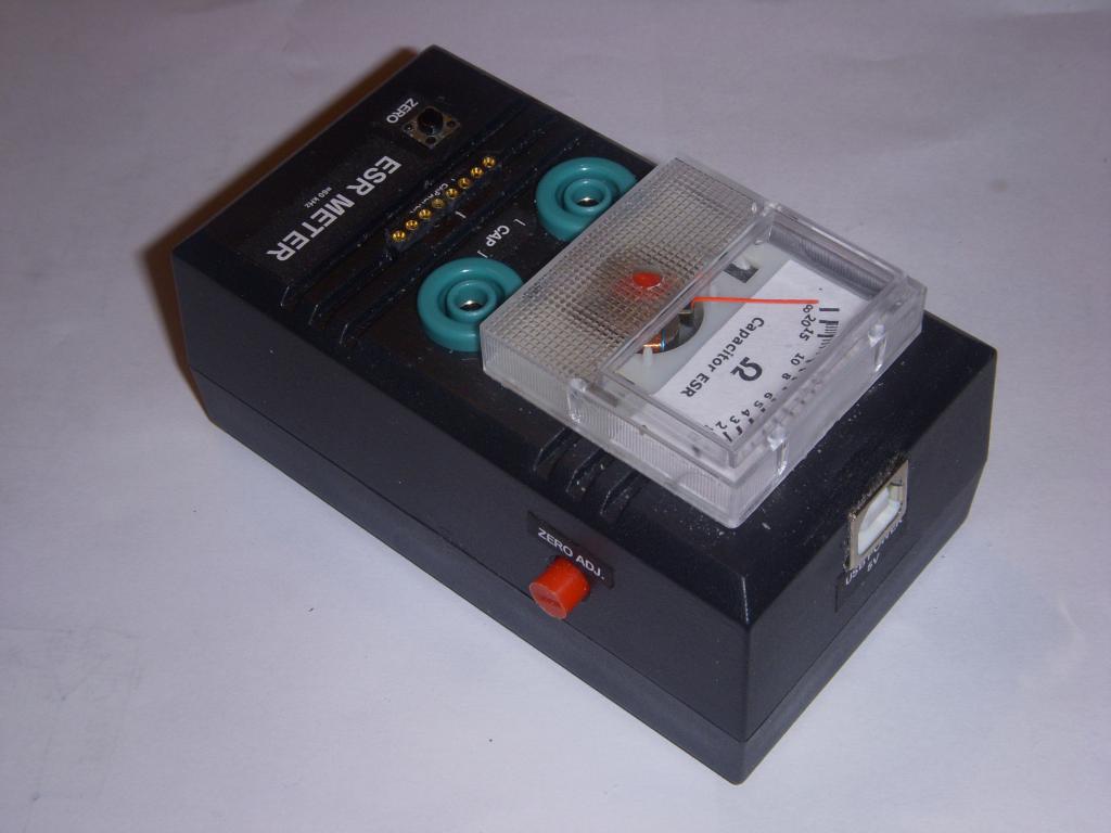 Outside view, top-side | 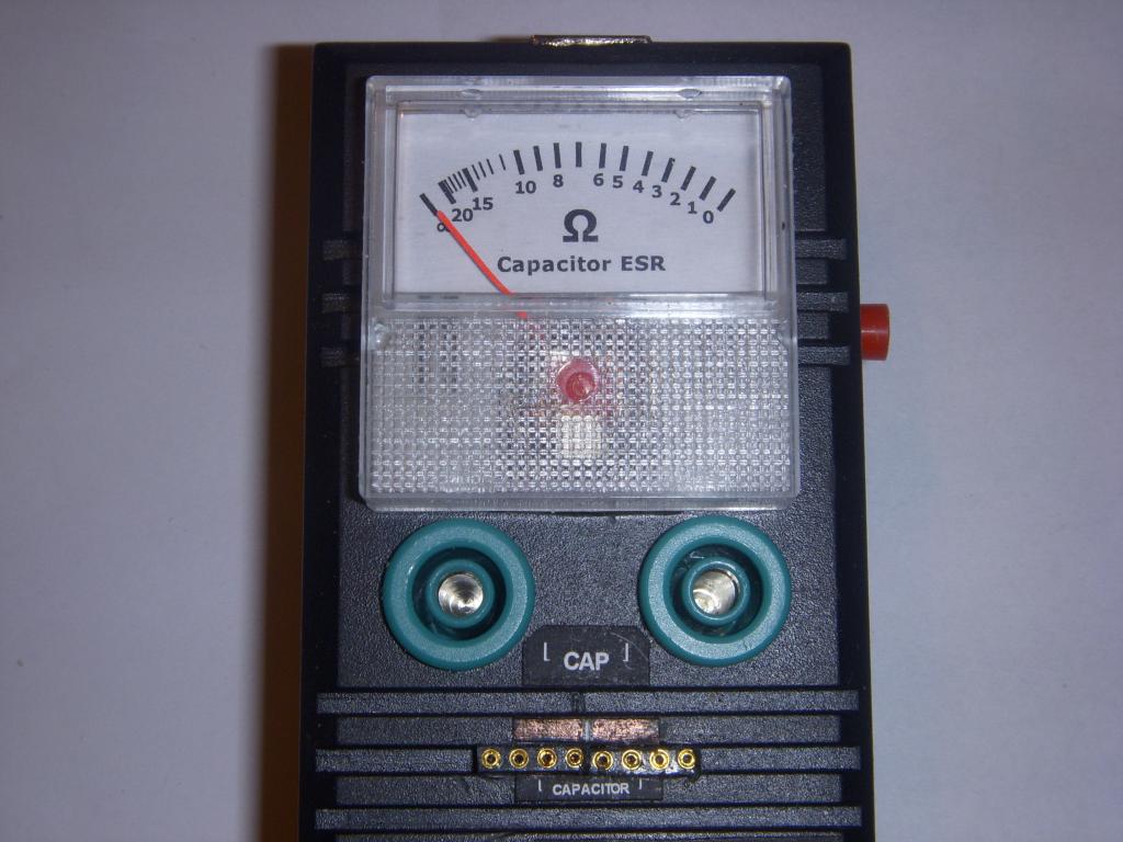 Front side | 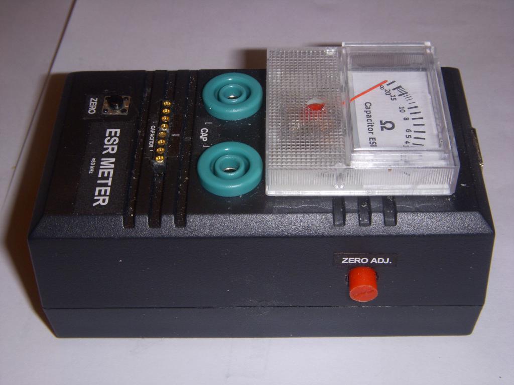 Outside view, side | 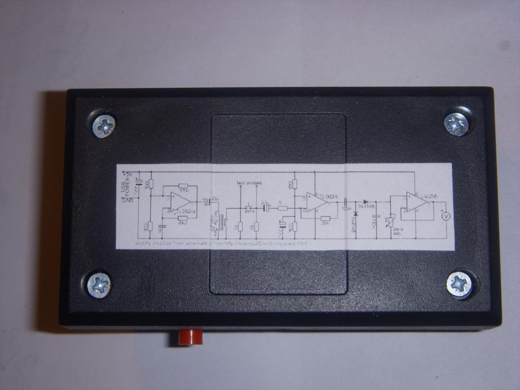 Outside view, bottom |
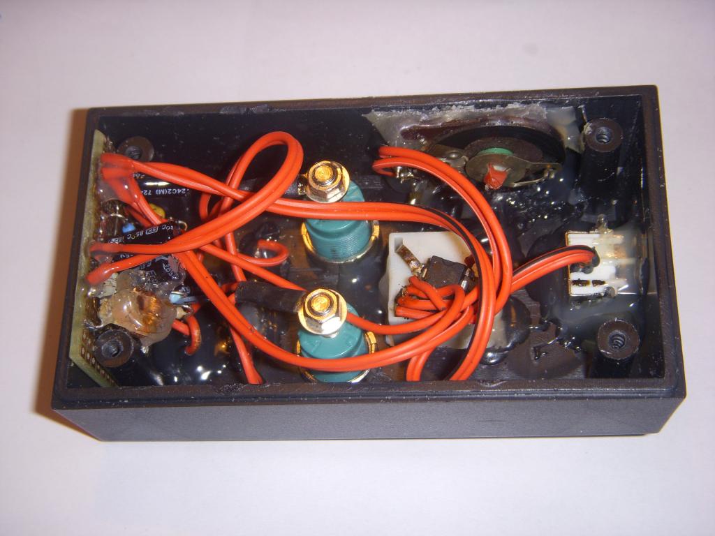 Inside view | 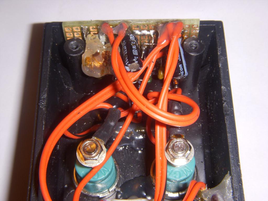 Inside view, electronics, detail | 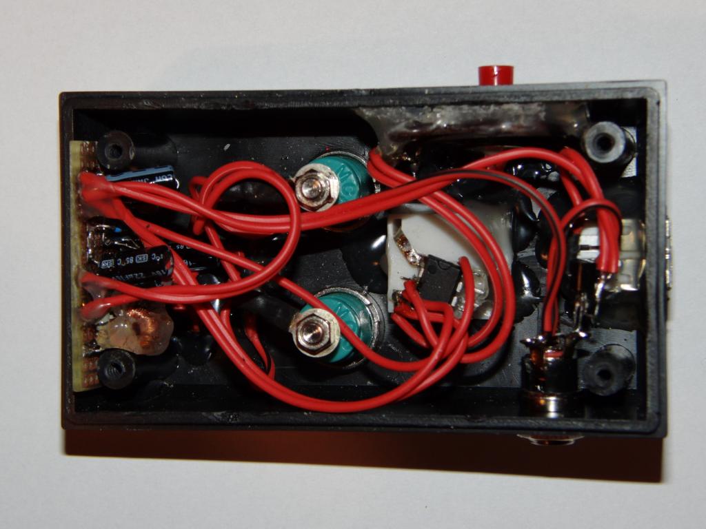 12V power connector, inside view | 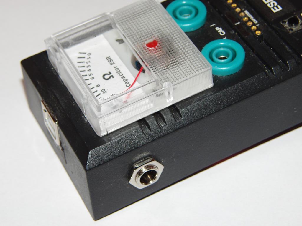 12V power connector, outside view |