IrDA monitor
What, why
During debugging of IrDA setups, it is occassionally needed to see the communication occuring.
Infrared light has a significant disadvantage of not being human-visible, and IrDA communication
devices have too narrow radiation pattern to make use of digital cameras as infrared detectors
reasonably comfortable. However, a quick oscilloscope check on the disassembled USB dongle shown
the presence of clearly defined send and receive signals between the transceiver and the chip.
Adding a suitable buffer and a pair of LEDs was an obvious solution.
setups, it is occassionally needed to see the communication occuring.
Infrared light has a significant disadvantage of not being human-visible, and IrDA communication
devices have too narrow radiation pattern to make use of digital cameras as infrared detectors
reasonably comfortable. However, a quick oscilloscope check on the disassembled USB dongle shown
the presence of clearly defined send and receive signals between the transceiver and the chip.
Adding a suitable buffer and a pair of LEDs was an obvious solution.
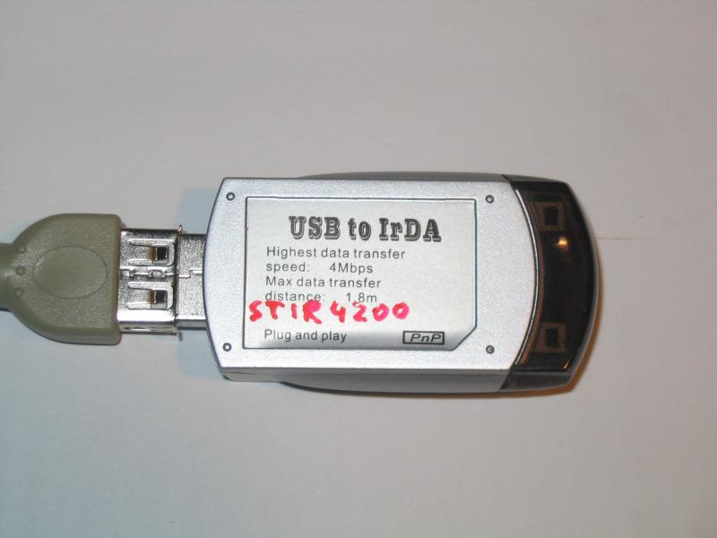
In our case we used a generic-looking nonamish IrDA dongle. In Linux, it uses the stir4200.o module.
Construction
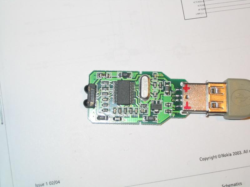
First we need to identify the presence of the signals. We take the dongle apart and connect it
to the USB cable. We run two series of tests, one with no device in range, which lets us identify
the Tx (transmit) signal, the other with a suitable device in range (in our case a Nokia cellphone)
which allows us to see the Rx (receive) signal too. We want to identify signals that are clear and
square. The signals look like narrow pulses. They may be both active-high and active-low, and may be
either 5V or 3.3V. In our case, the Tx signal was found to be active high with 5V levels, and the
Rx was active-low 3.3V. This influenced the connection of the LEDs to the buffer.
Once we identified the signals, we had to select the suitable buffer. The original intention was
to use a circuit with a LED and a NPN transistor for each line. However that turned out to be
too complicated, both electrically and mechanically, so a driver chip was chosen as another option.
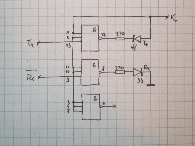
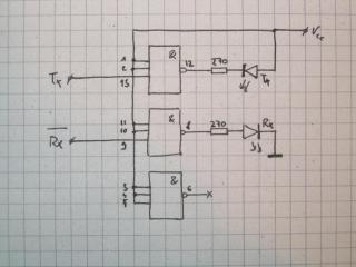
The chip chosen was 74HC10, a triad of three-input NAND gates. The choice was determined by the
availability of a chip (I had one on hand), and its high input impedance which poses minimal load
to the original circuit.
Two of three NAND gates were used. One input of each gate was connected to the respective signal
on the board, the other inputs were connected to logic H. All inputs of the unused gate were tied to H
in order to prevent oscillations.
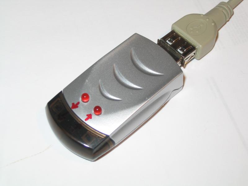
The outputs of the gates were connected to the indicator LEDs via 270-ohm resistors. The LEDs are
3mm red low-power ones to achieve decent light output even with small current and short impulses.
As we have the Rx input active low and the Tx one active H, the LEDs are connected to light up when
the Tx output is L and the Rx output is H (the NAND gates are inverting).
It was discovered that there is enough clearance between the board and the case to fit a PDIP chip
inside, when its pins are bent to sides. The bottom side of the chip was glued to the case with
a drop of hot melt glue. The diodes were put into holes drilled in the case and their pins were
bent to the sides and cut to suitable lengths (see image). Thin enameled wire was used to connect
the +5V and ground from the USB connector to the chip power pins, and to connect the Rx/Tx signals
from the board. The resistors used were chosen to be SMD, the 0805 size, in order to achieve minimal
size and comfortable mounting.
Possible improvements
We may add a pulse width stretcher and tap the signals so they can be wiretapped on by a RS232 port.
This may serve for advanced debugging and protocol analysis.
We may connect the outputs to a piezo, so we can hear the buzzing of the signals. This may prove
to be more useful for advanced development, as the ear is better to recognize characteristic high-speed
patterns than the eye.
Outstanding question
Why is the optical indication of Rx/Tx signals not a standard feature of off-the-shelf equipment?
It makes the debugging significantly easier, and it is a nice set of
blinkenlights to watch with delight.
Full disclosure: I love blinkenlights.
Images
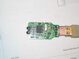
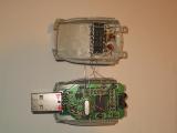
Original board, top side | 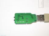
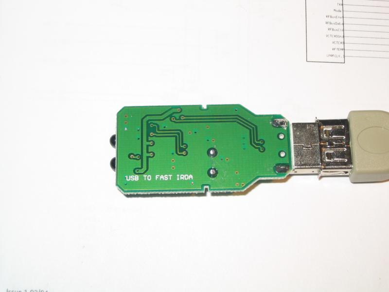
Original board, bottom side | 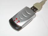
Final device, top side | 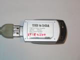
Final device, bottom side |
Board top side, wiring points | 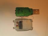
Board bottom side, wiring point |
Schematics | 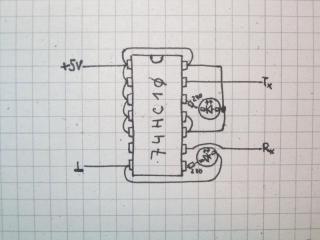
Chip wiring diagram |
| If you have any comments or questions about the topic, please let me know here: |