A pressure sensor was providing output as a DC voltage in the 1..10V range. It died. The only available replacement provided output in 0..10V range. A board was designed to convert the output ranges.
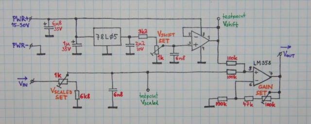
The board consists of three functional modules: an input scaler, a reference
source, and an adder. The input signal is scaled from 0..10V range to 0..9V, by
the means of a resistive divider. The reference voltage, used to shift the input
by a DC offset, is generated with a 78L05 stabilizer and then scaled down to 1V
with a resistive divider. To avoid coupling with the signal input the reference
voltage is buffered with an op-amp. A common, cheap LM358 dual op-amp is used.
The DC offset and the downscaled signal are then added and amplified again, using a common 1:1 adder circuit. To compensate for the tolerances of parts the gain of the op-amp is adjusted with a trimpot.
To suppress noise, low-value capacitors are added to a few places in the circuit (to input side only to prevent capacitive loading of the op-amp output).
The PWR+ and PWR- terminals are to be connected in parallel to the power terminals of the sensor. (Beware, there is no protective diode included, do not mistake polarity!)
The sensor output connects to the "Vin" terminal. Scaled signal is taken from the "Vout" terminal.
The "Vshift" and "Vscaled" pins are used for adjustment. The Vshift terminal has to show 1.00 volts (or the desired value of DC offset). The Vscaled terminal has to show 0.9 times the Vin voltage (9 volts for 10V input). The "Vshift set" and "Vscaled set" trimpots are used for setting these values.
The "Gain set" trimpot is used for setting the output voltage once the shift and scale pots are set. Use 10.00V on Vin (with 9.00V on Vscaled), and adjust Gain set until the Vout is at 10.00V.
Check settings with other input values; e.g. Vin=5V should yield Vout=5.5V (0.9*5+1), Vin=1V yields Vout=1.9V (0.9*1+1), Vin=9V should yield Vout=9.1V (0.9*9+1).
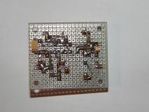 Board | 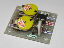 Board | 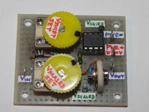 Board | 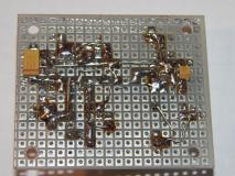 Board |
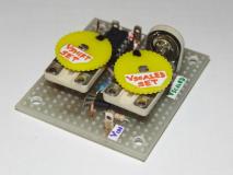 Board | 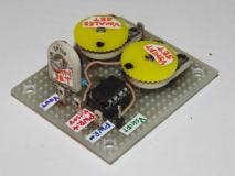 Board |