 is a surface with light evenly shining through. It is used
for looking at film, diapositive slides, xray films, tracing stuff on paper, and many
other purposes.
is a surface with light evenly shining through. It is used
for looking at film, diapositive slides, xray films, tracing stuff on paper, and many
other purposes.
A light table is a surface with light evenly shining through. It is used
for looking at film, diapositive slides, xray films, tracing stuff on paper, and many
other purposes.
A thin, lightweight and easily portable light table was desired to have in a workshop.
A liquid crystal display is a light table, with a LCD panel laid over it.
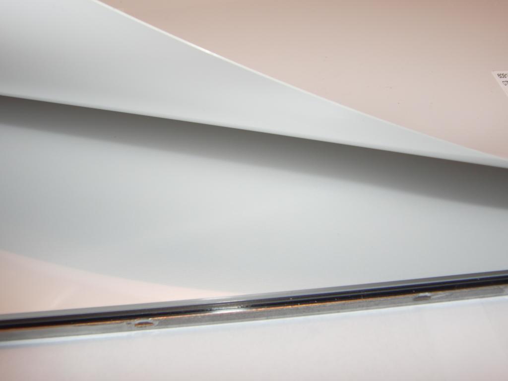
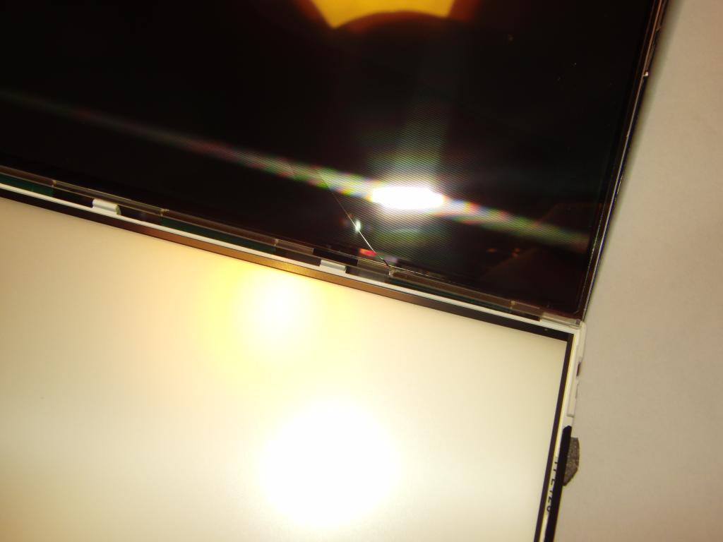
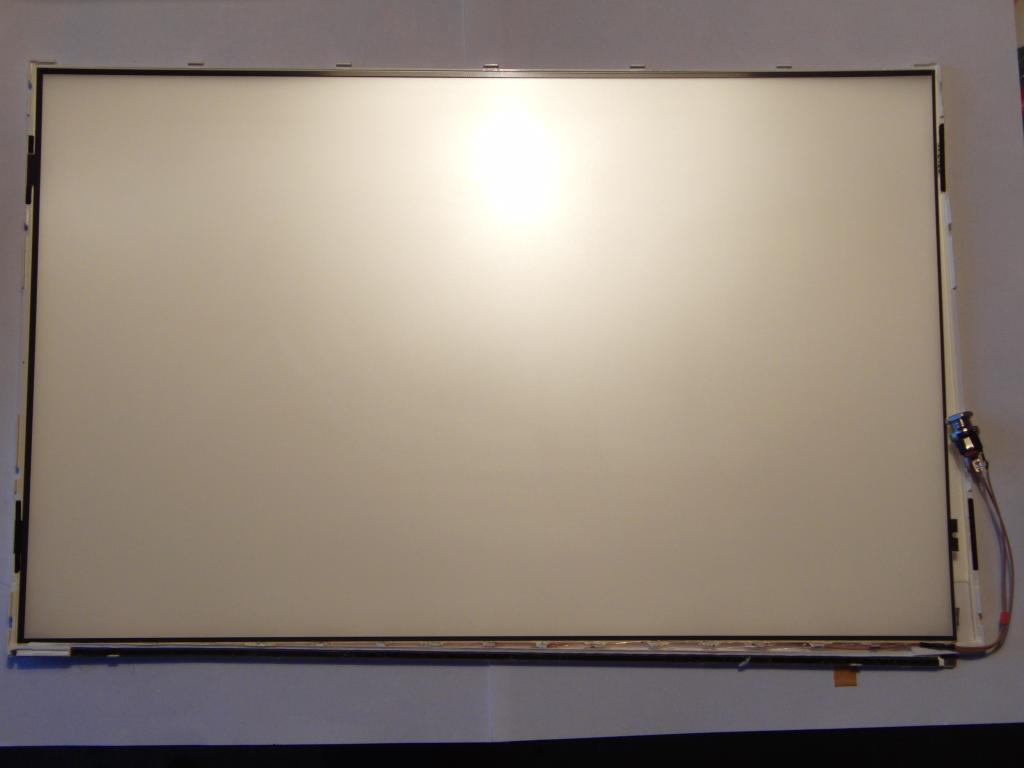
Several discarded LCDs were obtained from a laptop repair shop. The displays were all
cracked and the backlight CCFL tubes were either missing or broken. The backlight
diffusers, made from optical-quality plastic and several layers of micropatterned foils,
were however intact.
The cracked LCD panel was removed and set aside for salvaging the polarizing filters .
The backlight tube was removed.
.
The backlight tube was removed.
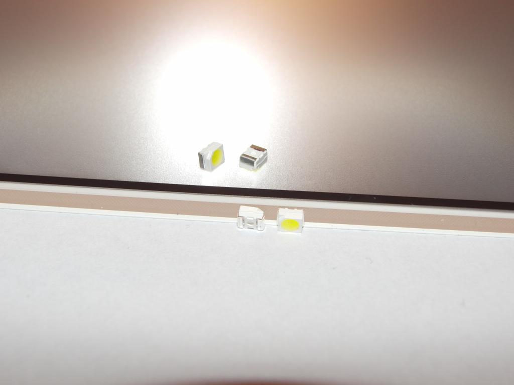
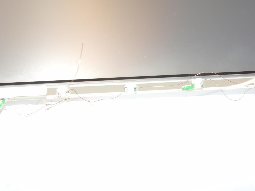
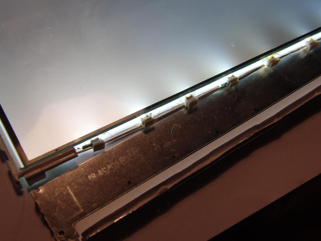
White SMD LEDs in the PLCC2 case (120°, 600-1200 mcd, ~3.3V, 20mA) were obtained. 20 pieces was bought, 15 were needed. (This turned out to be wise, as one was killed in early testing when an order of magnitude smaller resistor was used. The diode lit up very bright, then in matter of seconds its brightness gradually diminished to almost zero, when the test was ended.)
As the desired operation was from a 12V power supply, the topology was decided to be five strings of 3 LEDs each, with a 100-ohm resistor. 1206 SMD resistor was chosen, and attached directly to the terminal LED in the chain. Thin enameled wire was used to interconnect the LEDs. (In retrospect, a long thin strip of copper-clad would be better.) Five chains were prepared, with terminal wires of uneven lengths but adding to the width of the display panel bottom, with some added reserve. The ends of the chains were soldered together.
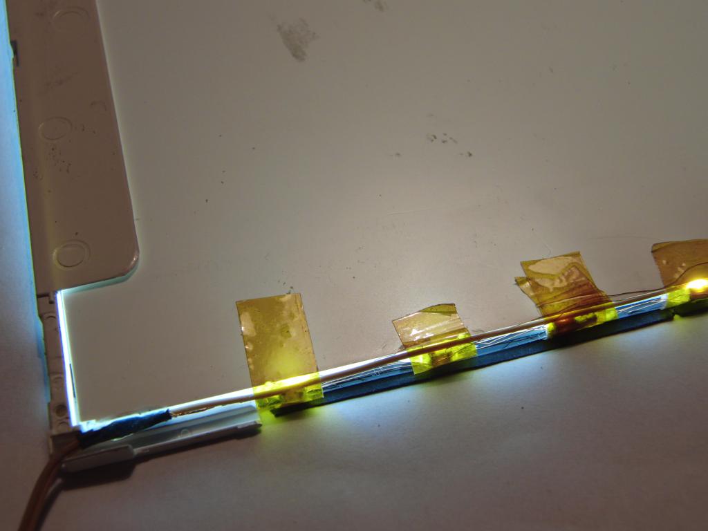
The LEDs were bonded to the side of the diffuser. Hot glue was attempted with low success; it did not satisfyingly bond to the LED cases. Using little pieces of adhesive foams on the LED backsides together with the original fluorescent tube holder to press them against the diffuser was also found to not be optimal. At the end, individual pieces of kapton tape were used to hold the LEDs in place.
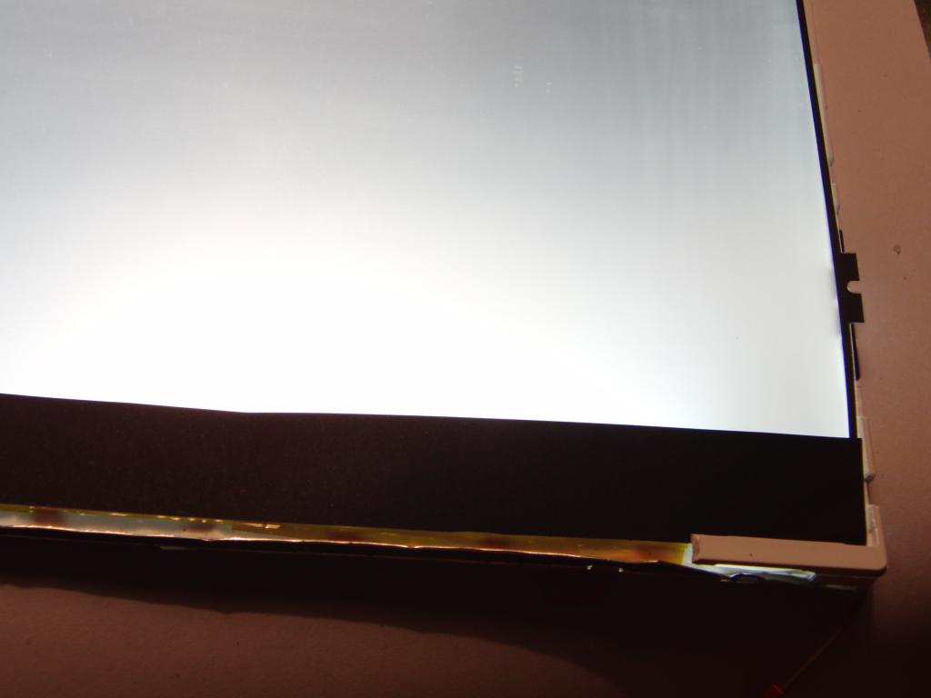
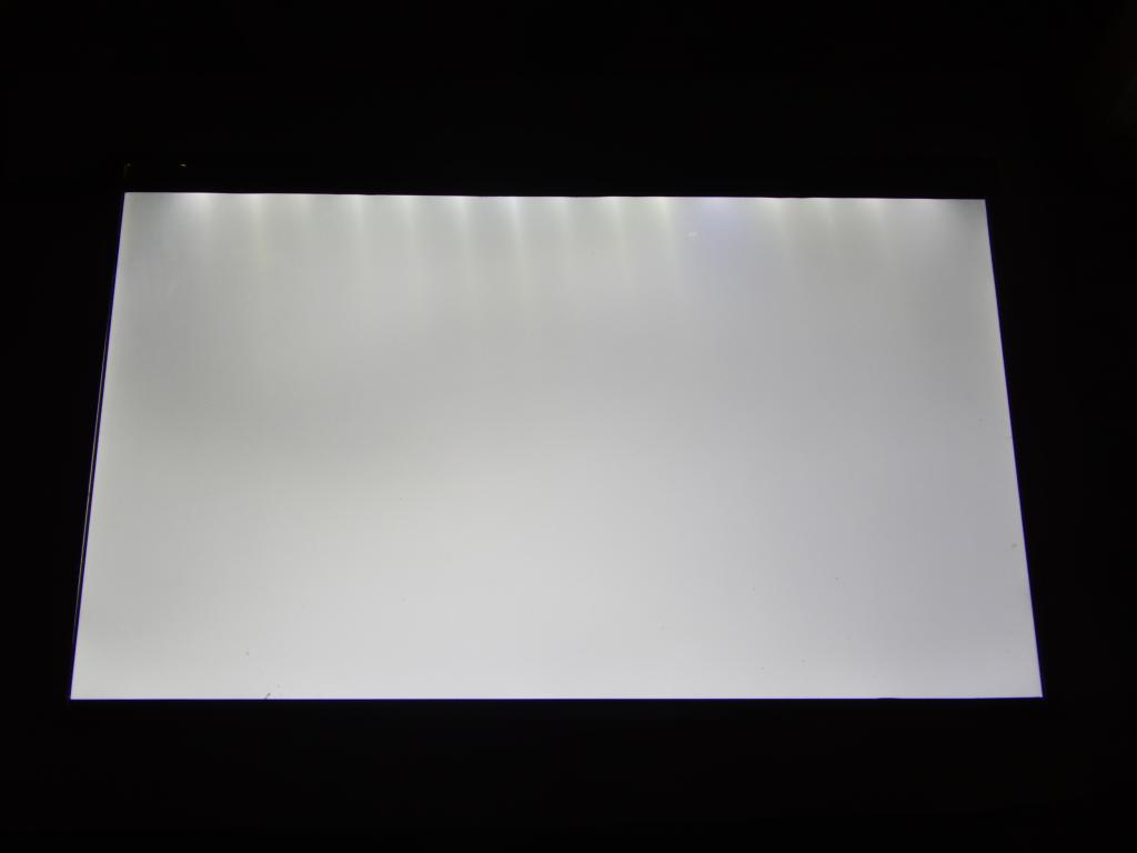
A strip of black paper was placed over the LEDs and a centimeter-wide strip of the diffuser, to conceal the uneven light cones coming from the LEDs. A thin strip of black tape was used on the other side to mask the light leakage from the other end of the backlight.
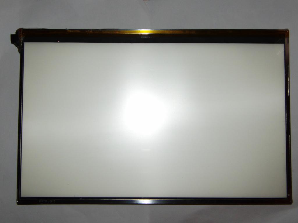
A layer of 2mm thick glass, cut to exactly the size of the original LCD panel, was placed over the backlight, to serve as the work surface of the table. The aluminium frame of the display was then placed over the assembly. As it was found that the assembly is now a little bit thicker than the original, and the latches on the frame do not clip on anymore, adhesive tape was used to hold the frame to the bottom of the assembly. This turned out to be an expedient but surprisingly workable solution.
As the glass panel was found to be exactly matching the inner edge of the frame, a length of kapton tape was used to hold them together. This is an artefact of bad measurement, using the display panel as a master instead of the inner side of the frame. (Lesson learned.) The tape however does the job of holding the parts together well.
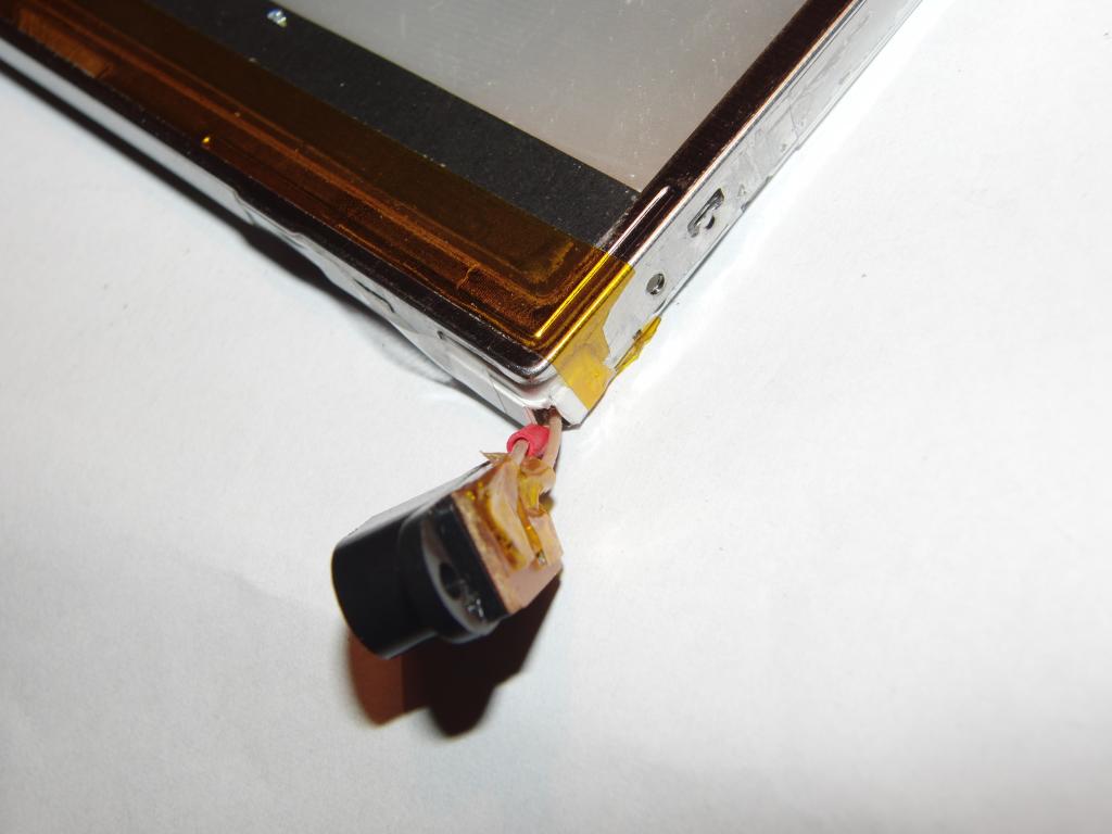
A 12V 2.1mm barrel connector of the cheapest plastic kind was used as the power connector, and attached to the side of the assembly with hot-melt adhesive.
The table produces fairly good amount of light and consumes only 100-120 mA at 12 volts.
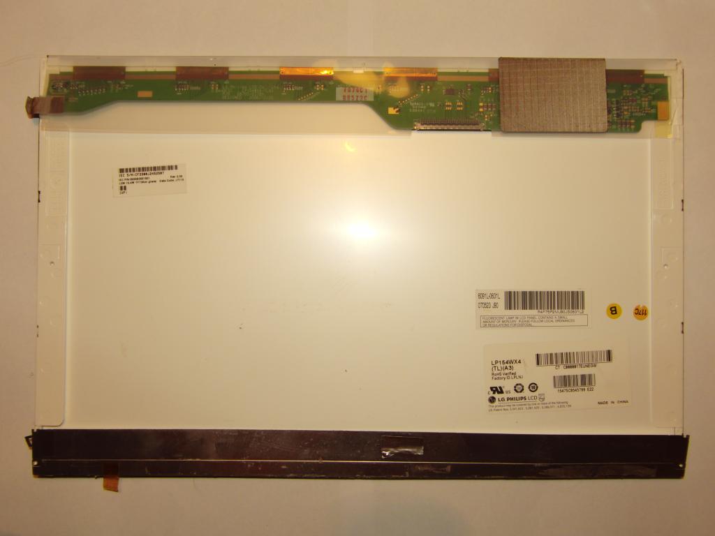 LCD panel, back side | 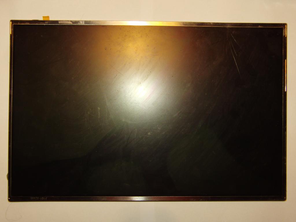 LCD panel, front side | 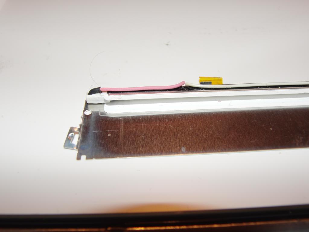 Backlight tube, detail | 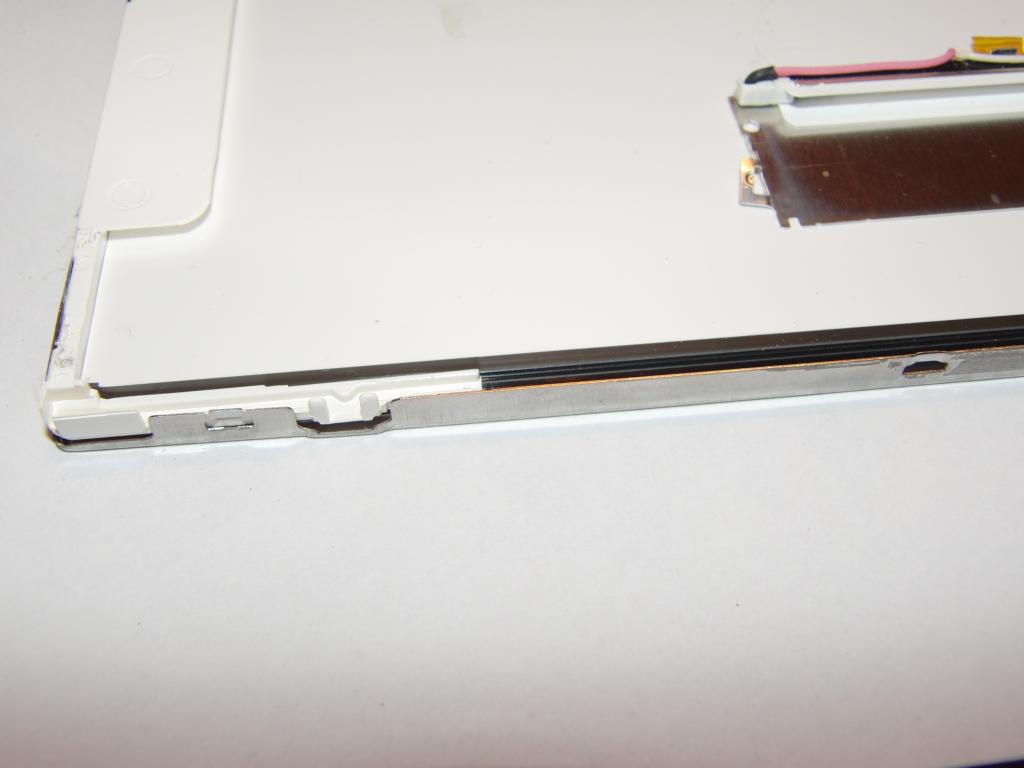 Backlight tube, placement |
 Diffuser backside | 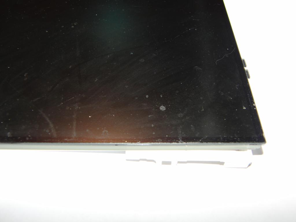 LCD without frame | 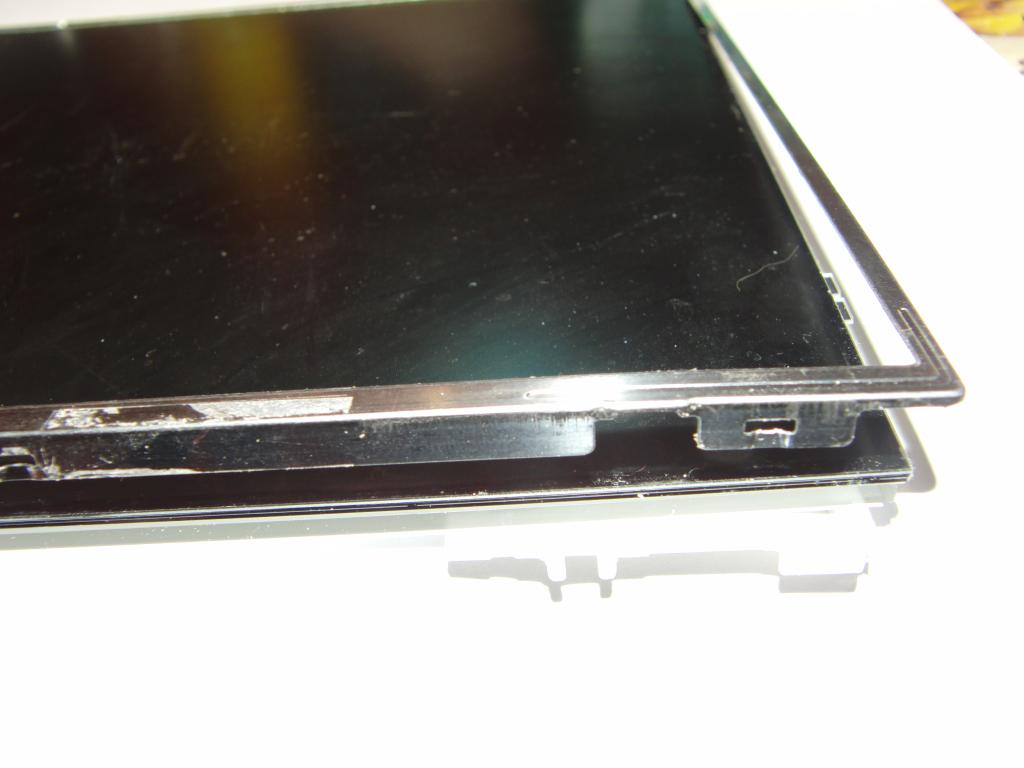 LCD frame position | 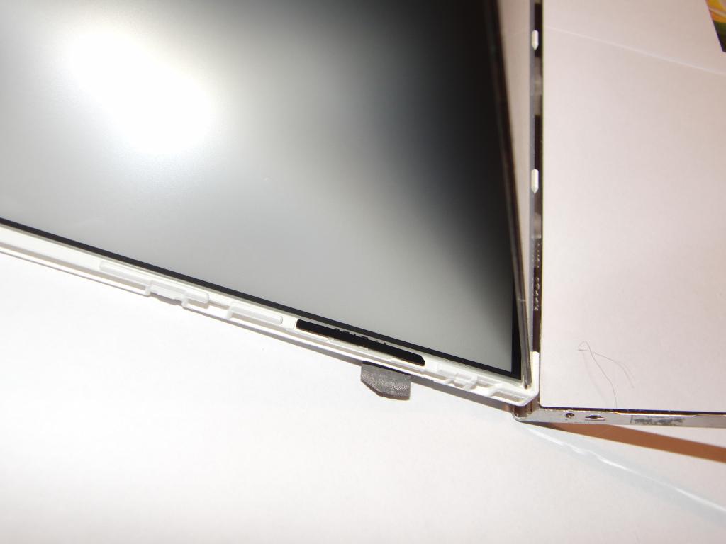 LCD frame position |
 LCD panel flipped off | 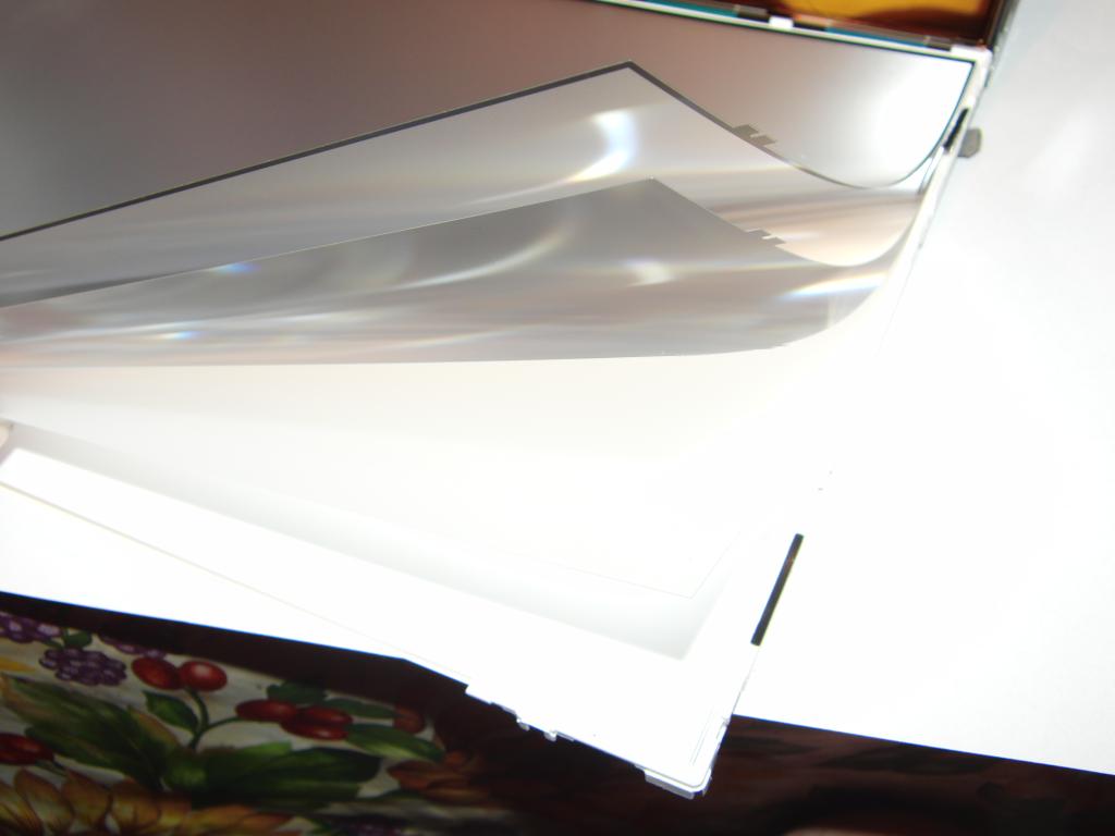 Diffuser layers | 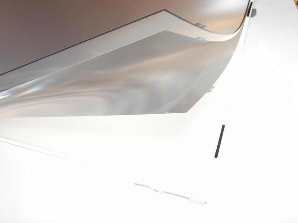 Diffuser layers | 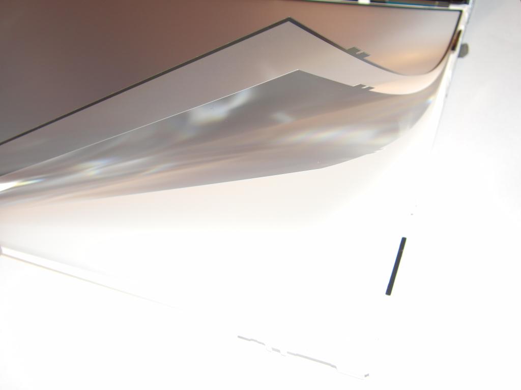 Diffuser layers |
 LEDs, side of the diffuser | 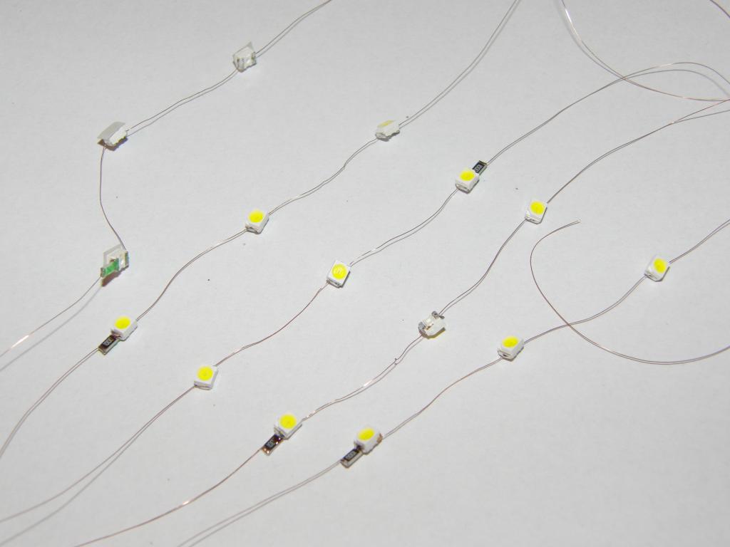 LED strings | 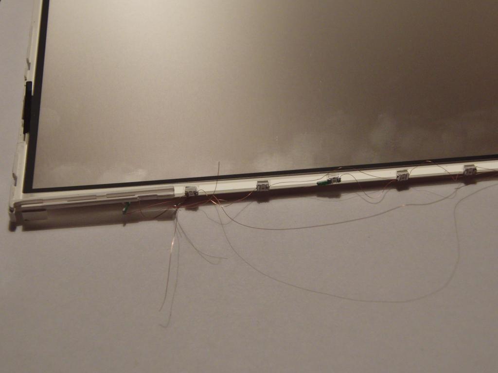 LEDs in place | 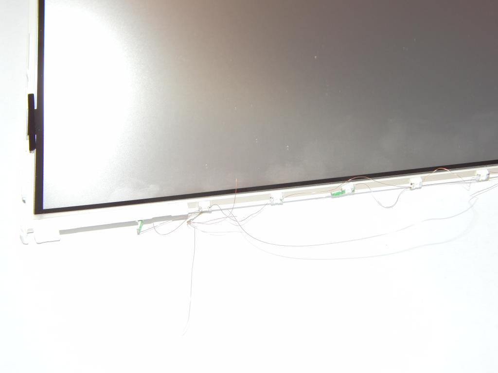 LEDs in place |
 LEDs in place | 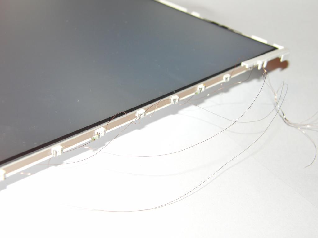 LEDs in place | 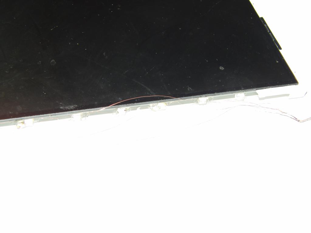 LEDs in place | 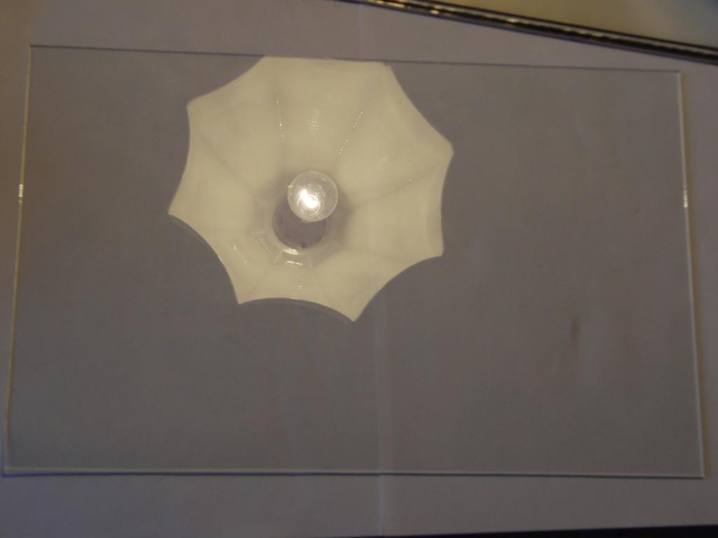 Glass panel |
 Backlight panel | 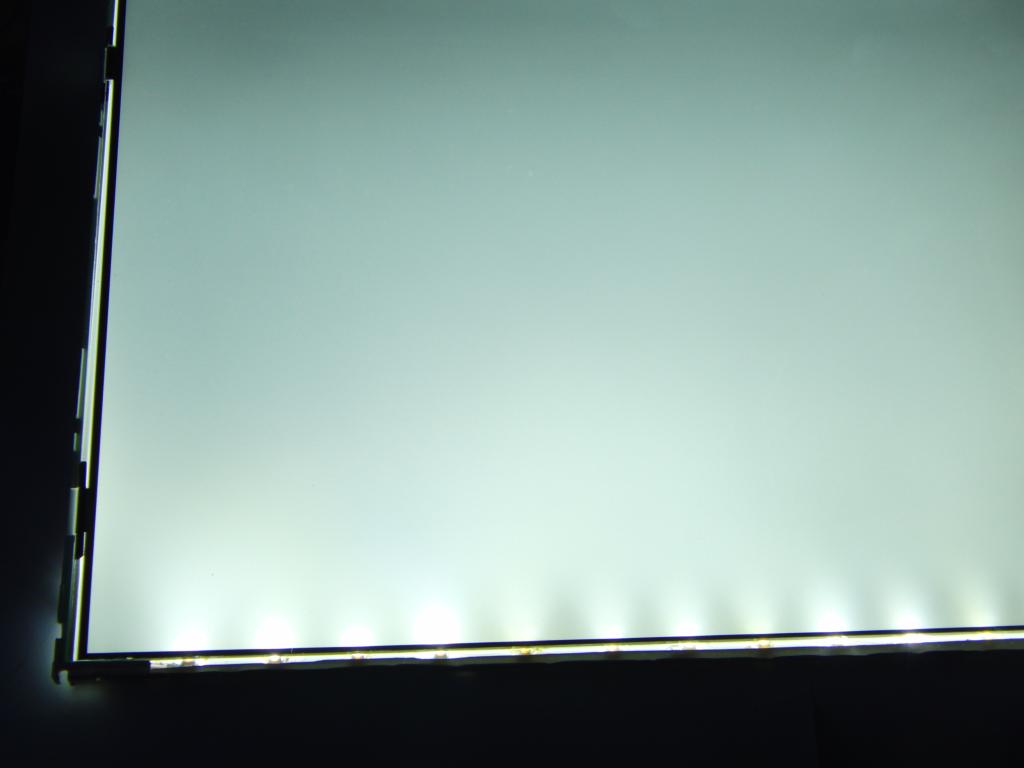 Backlight, LEDs operating | 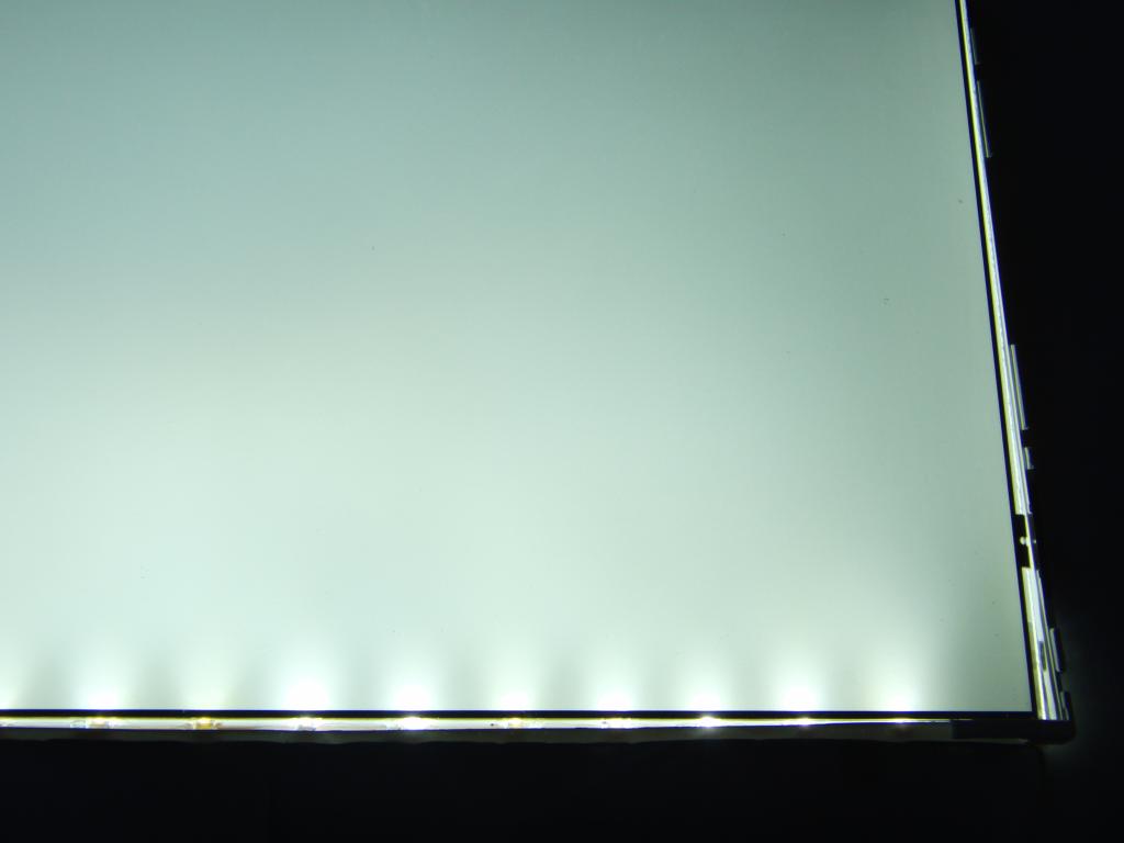 Backlight, LEDs operating |  Backlight, LEDs operating |
 Backlight, LEDs operating, hot-glue detail | 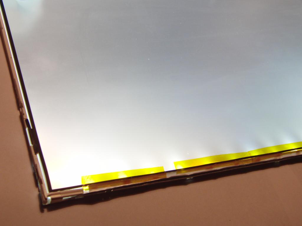 LEDs, cover taped in | 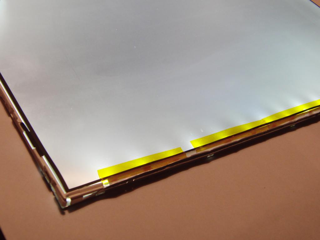 LEDs, cover taped in | 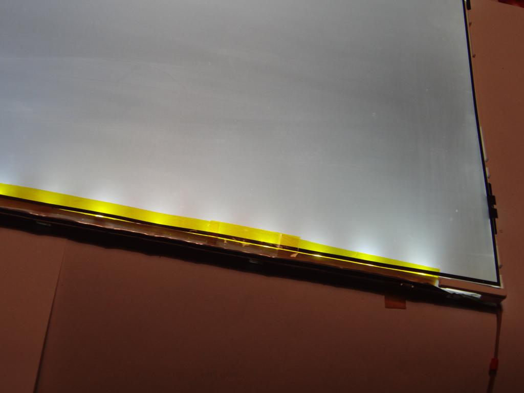 LEDs, cover taped in |
 Black mask strip over the LEDs | 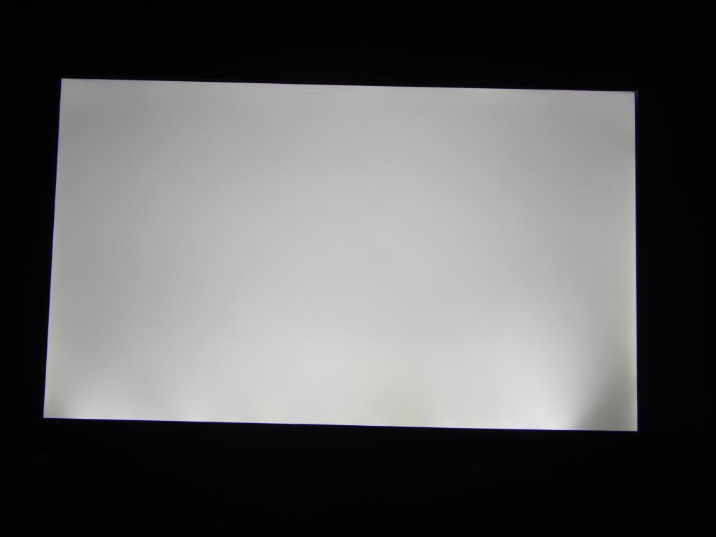 Backlight with two rightmost LEDs nonworking | 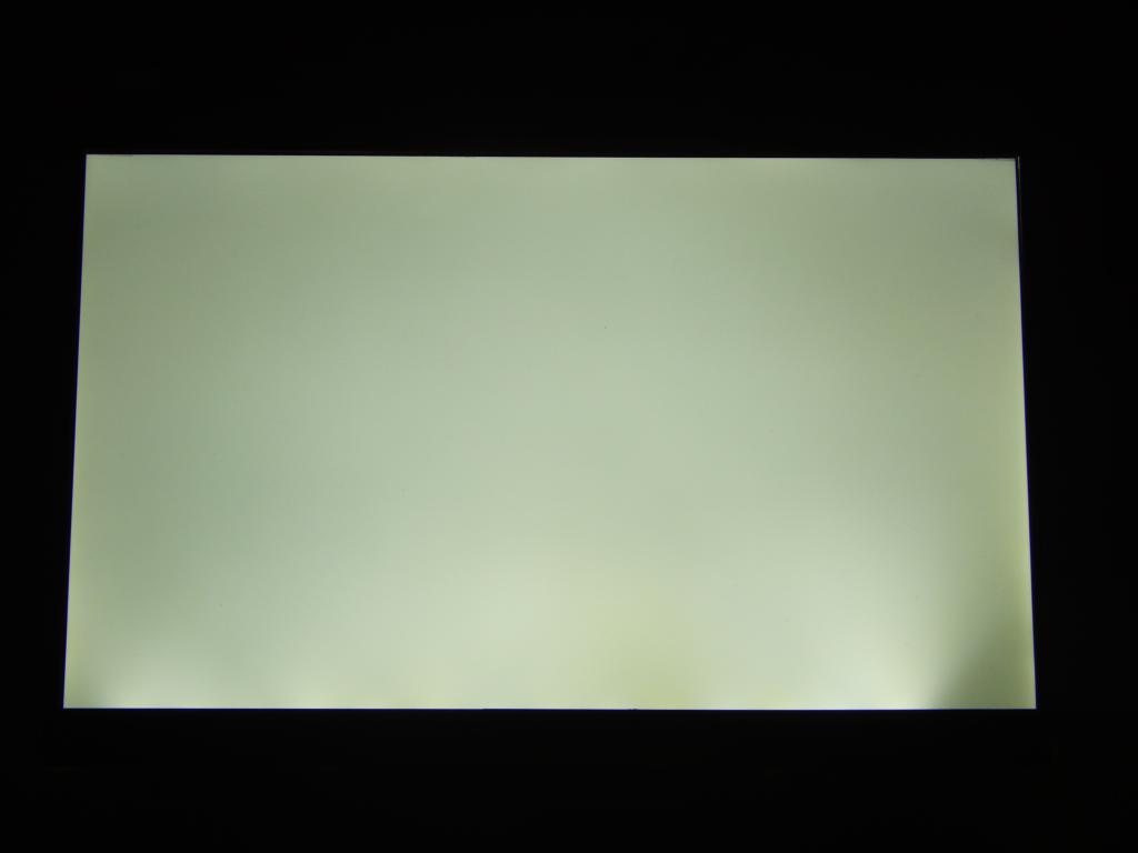 Backlight with two rightmost LEDs nonworking | 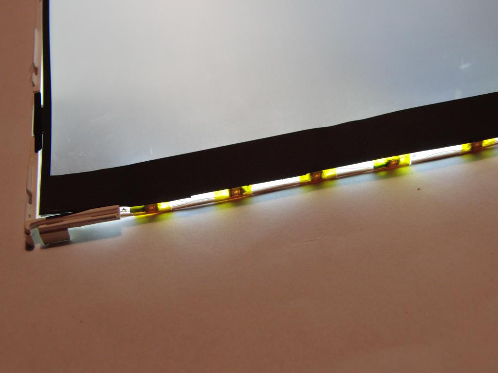 LEDs taped in place |
 LEDs taped in place | 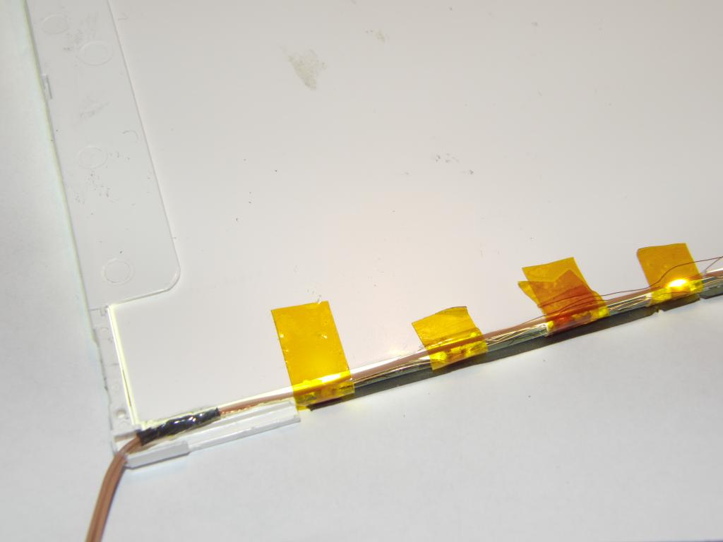 LEDs taped in place | 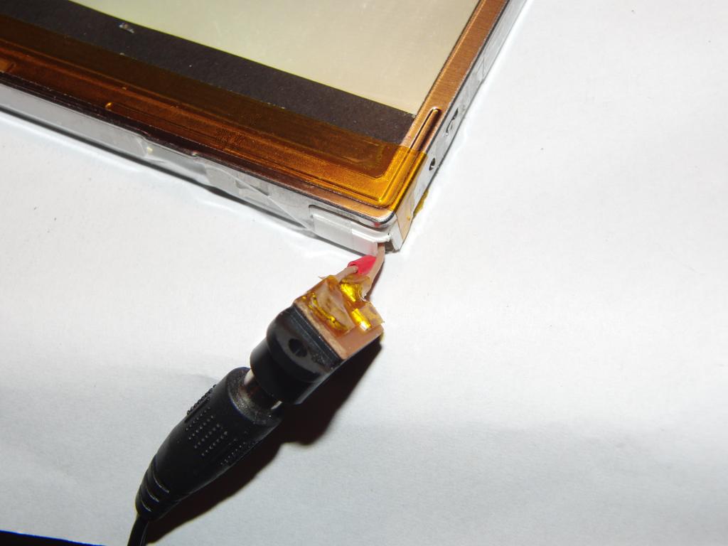 Power connector | 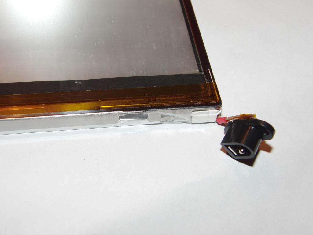 Power connector |
 Power connector | 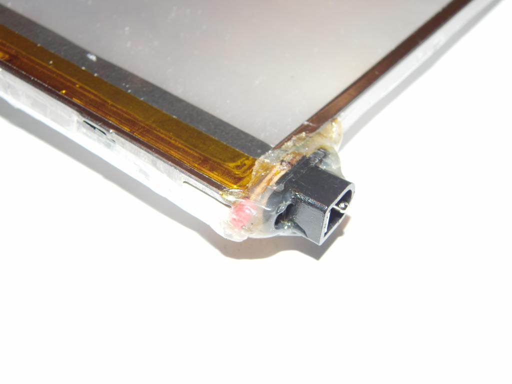 Power connector | 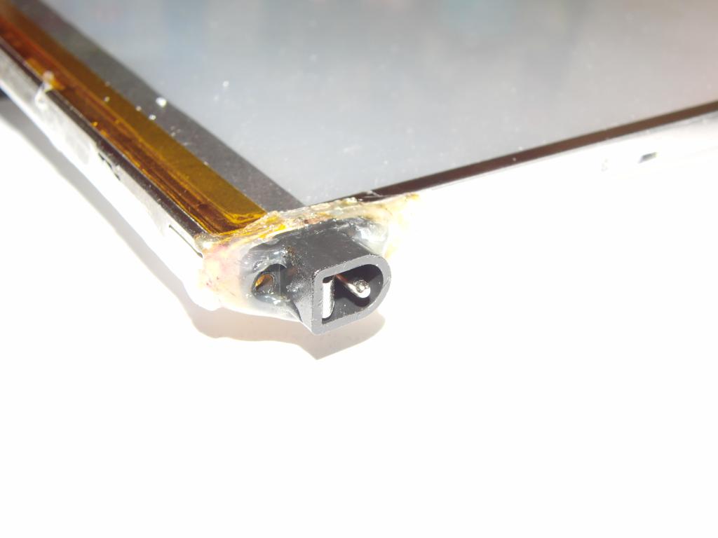 Power connector | 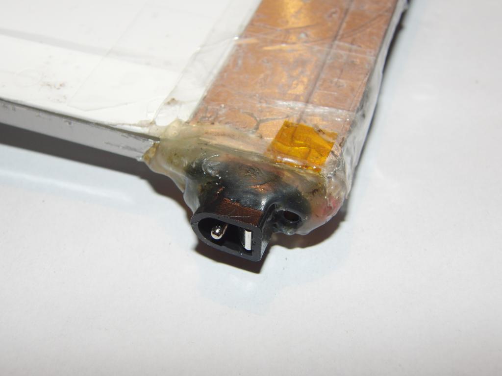 Power connector |
 Finished light table | 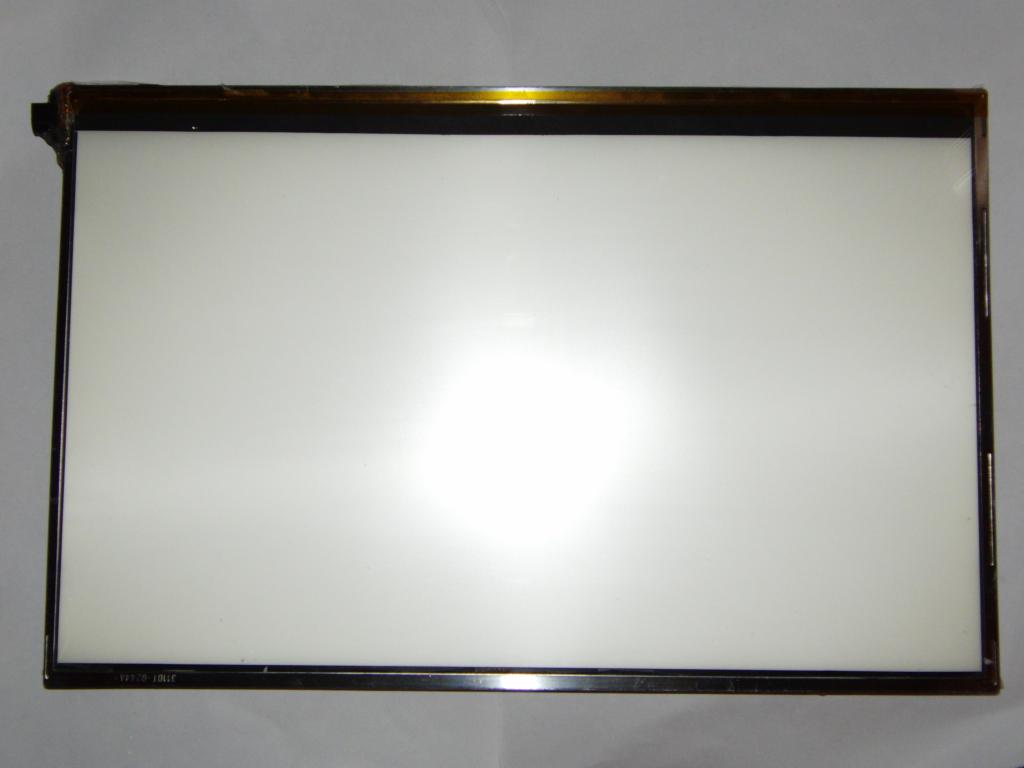 Finished light table | 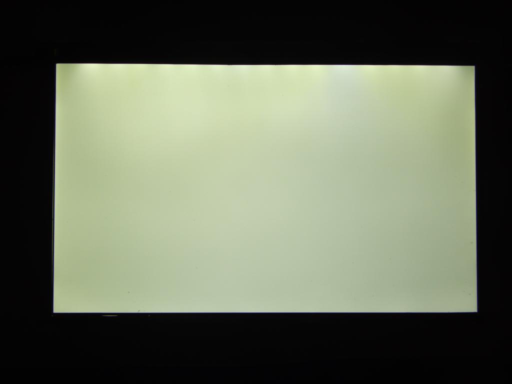 Finished light table, in operation | 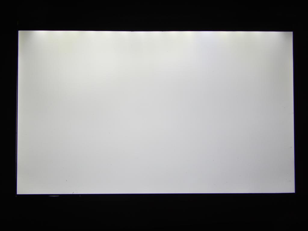 Finished light table, in operation |
 Finished light table, tilted to show the LED lights | 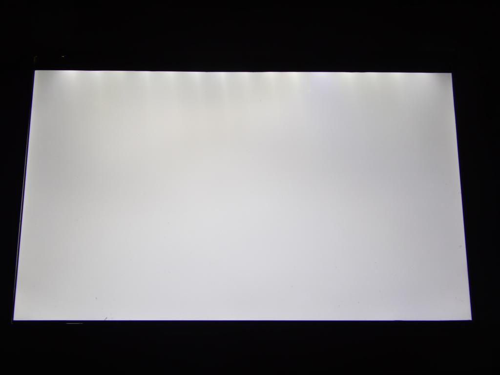 Finished light table, tilted to show the LED lights | 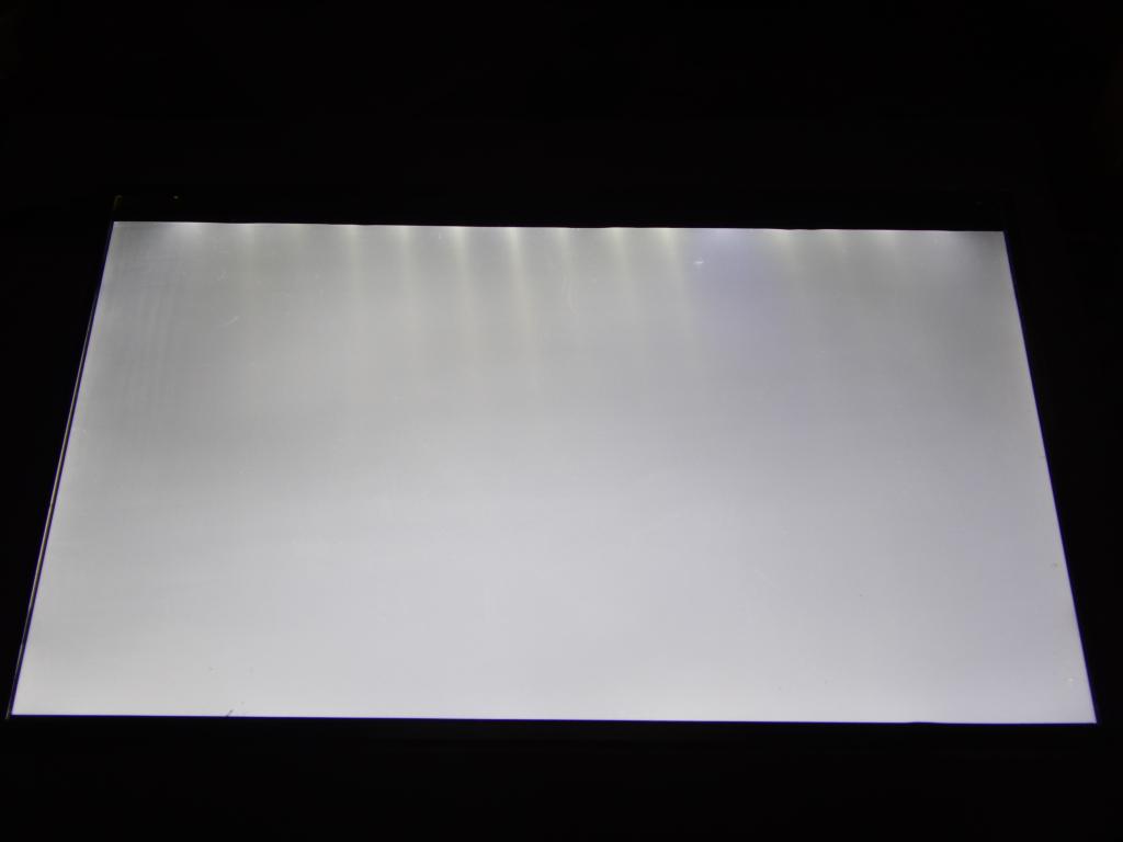 Finished light table, tilted to show the LED lights |