In design and repair of mains-powered hardware, there comes the inevitable moment when the device has to be powered up. This is the most critical moment; any mistake or failing part can cause higher than intended energy consumption, leading to release of magic smoke, spark and flame effects, and tripped breakers. As such surprises are costly and generally unpleasant, something that limits the maximum current through the device would be an advantage.
This something, a trick well-known between old-school repairmen, is a humble lightbulb .
(An alternative for the hapless serfs in European Union, where lightbulbs are on the
index of gradually banned
technology, is the HEATBALL®
.
(An alternative for the hapless serfs in European Union, where lightbulbs are on the
index of gradually banned
technology, is the HEATBALL® .)
.)
Lightbulbs are load-dependent resistors. The resistance of the filament depends on its temperature, while the temperature depends on the current. A cold filament is about an order of magnitude less resistive than a fully hot one. A lightbulb that's loaded to only a fraction of its nominal current will present very low resistance; the resistor divider between the bulb and the device under test will have most of the mains voltage across the device. When the device's load gets higher, the current through the bulb increases, the temperature of the filament grows, its resistivity increases, and the bulb takes higher proportion of the mains voltage, not just limiting the maximum current through the circuit but also taking greater proportion of the consumed energy; the energy that'd otherwise be all deposited in the faulty parts of the tested device.
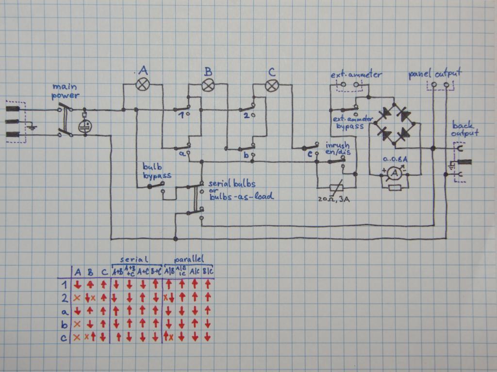
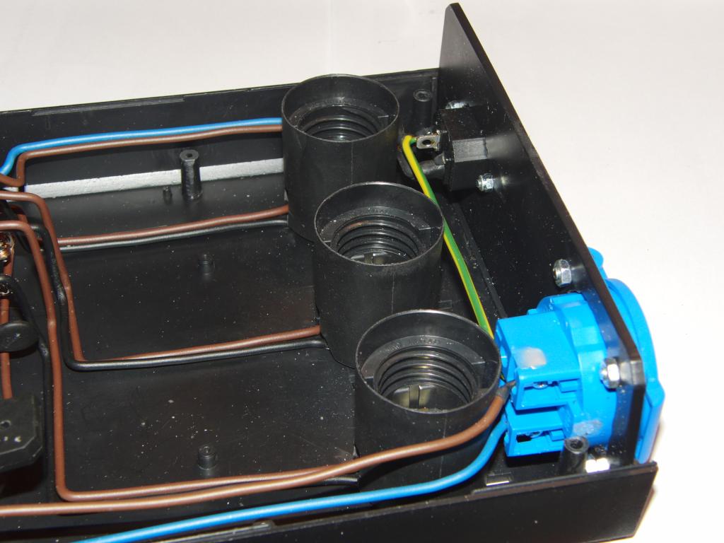
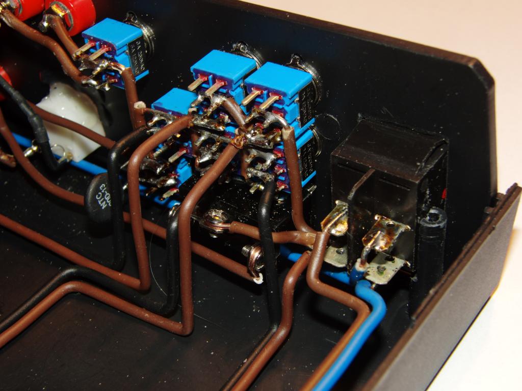
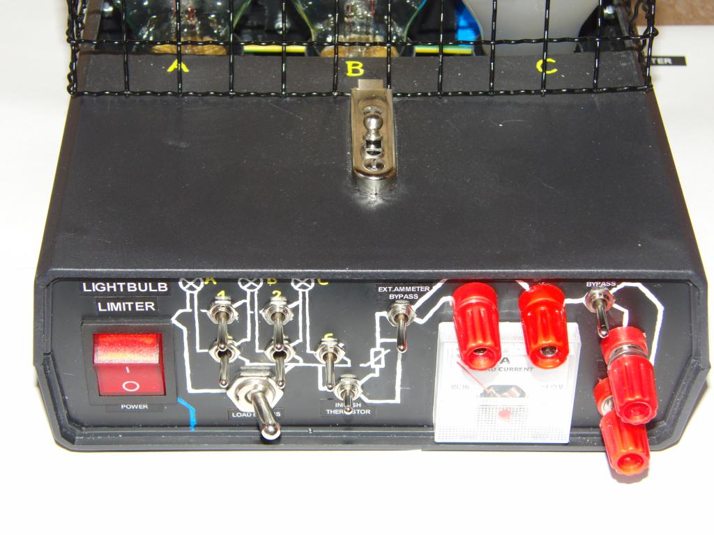
A tool was designed to facilitate easy testing of mains-powered devices. The unit contains three lightbulbs (their values can be arbitrarily chosen to suit the applications) and several switches that allow selecting the desired combination of the lightbulbs; single one, or a series or parallel combination of two or all three.
In addition, the tool contains a selectable inrush current limiter (a NTC thermistor, rated to 20 ohm/5 amps),
a built-in ammeter, and a pair of terminals for attaching an external ammeter or other device
connected in series with the load; these terminals can be bypassed with a switch. The entire
lightbulb set can be also bypassed by another switch, for the last test when the operator is
confident enough about the tightness of the magic smoke conduits.
Additional switch was added as an afterthought, to turn the unit into a dummy load. (The motivation
here was the number of cases when the unit was used with the output terminals shorted, with just the
lightbulbs used as a resistive load or power-on indicator.) The switch also acts as an interlock for
the load-bypass switch, so both can not be engaged at the same time (which would make the unit act
as a short circuit); when it is engaged, the load-bypass current path is interrupted.
For output, a standard European power socket was placed on the back panel, together with a pair of terminals on the front panel. This allows attachments of both finished devices with power cord, and individual components/boards with only bare leads.
The ammeter used was the cheapest panel meter on local market, originally with a 3-amp scale and shunt. The shunt was removed, the resistance of the meter was measured, the voltage across the coil needed for full needle deflection was empirically determined (connected in series with 1 kΩ trimpot and the trimpot adjusted to full deflection using 5V from the USB port, then the resistance of the trimpot as-set was measured, and the voltage across the meter calculated. A range for the meter was chosen (0.8 amps, picked up as a middle-of-the-road suitable value sufficient for most cases). The value of the shunt was calculated and cut from a length of manganin wire. The meter was then connected in series with a 5V power supply, an adjustable resistor, and a digital multimeter, and the current was adjusted to values between 0 and 0.8 amps, with 0.1 A step. A mock-up scale with preprinted angle markers was used and ticks were made on it, the angles then were used to print out a meter scale by a PHP application.
Caveat: Due to a mistake in thinking, the meter was calibrated with DC current and used with AC current. This makes it display the average value instead of the RMS value, which is about 10% lower. As the meter is only an indicator-grade, the error is at this moment considered acceptable; for more accurate measurements, an external ammeter should be used anyway.
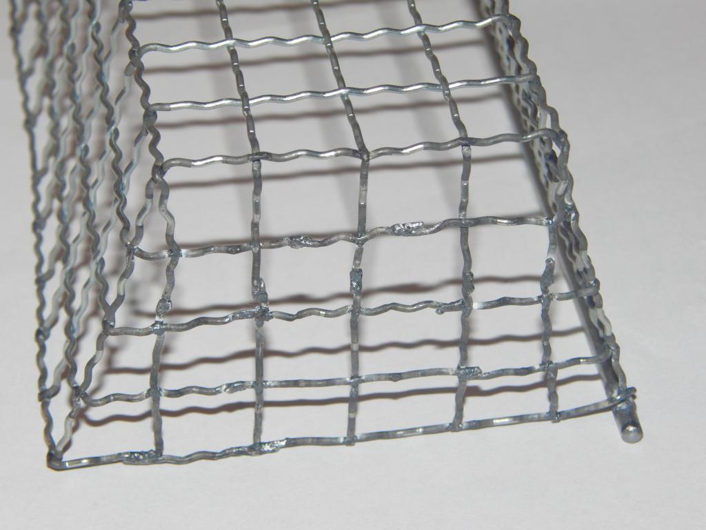
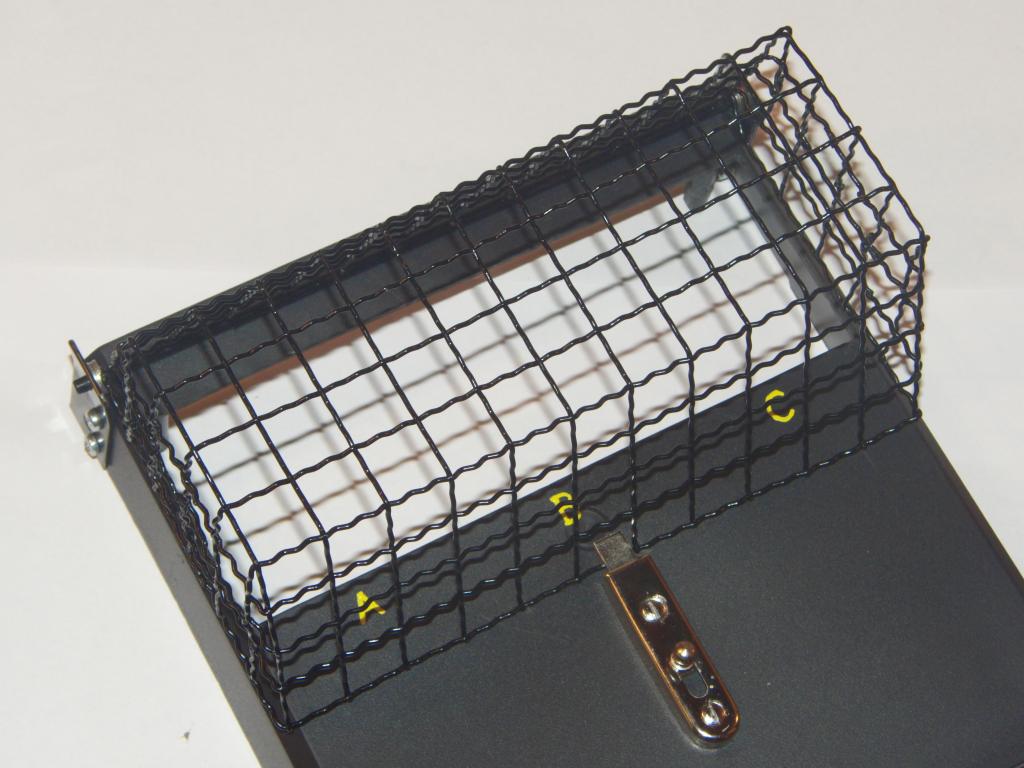
It turned out that the lightbulbs are too mechanically exposed. A protective cage was therefore designed.
A wire mesh was chosen as a compromise between mechanical integrity, cooling, ease of access, weight,
and material availability. Due to availability issues a device for assisting soaking paint rollers with
paint (a 4mm-diameter wire frame with a mesh of thinner, about 1mm thick wires) was used as the source of the material.
The mesh was welded only at its ends, to the frame; the wires themselves were loose, only intertwined.
For the original purpose it did not matter; however for a wire cage this could be fatal, as after cutting off the
supporting frame it could fall apart. A recently built spot welder was used for welding the mesh together at its crossings, along the future edges and the bends. The frame was then sawed and the required
part of the mesh was cut out. The outermost longitudal wires (two on one side, one on the other) were removed.
The sheet was bent twice in a vise, forming the cage profile. The protruding wires from the sides were bent to the
inside, forming the sides of the cage. Where needed, the wires were prolonged by welding stubs of wire to
their end. Wires were weaved to a mesh, forming the side panels, and welded at each crossing for increased
mechanical integrity (due to not optimal design of electrode holders of the welder, some points were rather difficult
to access). The protruding ends
of the remain of the 4mm frame were used for hinges; two small iron bars were used for the matching hinge parts; stacks
of M4 washers were used to adjust the precise width of the cage axis to prevent slipping out of the hinge.
A small latch was mounted on the top side of the device, to hold the cage closed while allowing its easy opening
for replacing or adjusting the lightbulbs. The cage and the hinges were spray-painted black for aesthetical
reasons and to protect the welds against corrosion (the zinc coating vaporized from these areas during welding).
was used for welding the mesh together at its crossings, along the future edges and the bends. The frame was then sawed and the required
part of the mesh was cut out. The outermost longitudal wires (two on one side, one on the other) were removed.
The sheet was bent twice in a vise, forming the cage profile. The protruding wires from the sides were bent to the
inside, forming the sides of the cage. Where needed, the wires were prolonged by welding stubs of wire to
their end. Wires were weaved to a mesh, forming the side panels, and welded at each crossing for increased
mechanical integrity (due to not optimal design of electrode holders of the welder, some points were rather difficult
to access). The protruding ends
of the remain of the 4mm frame were used for hinges; two small iron bars were used for the matching hinge parts; stacks
of M4 washers were used to adjust the precise width of the cage axis to prevent slipping out of the hinge.
A small latch was mounted on the top side of the device, to hold the cage closed while allowing its easy opening
for replacing or adjusting the lightbulbs. The cage and the hinges were spray-painted black for aesthetical
reasons and to protect the welds against corrosion (the zinc coating vaporized from these areas during welding).
operation.
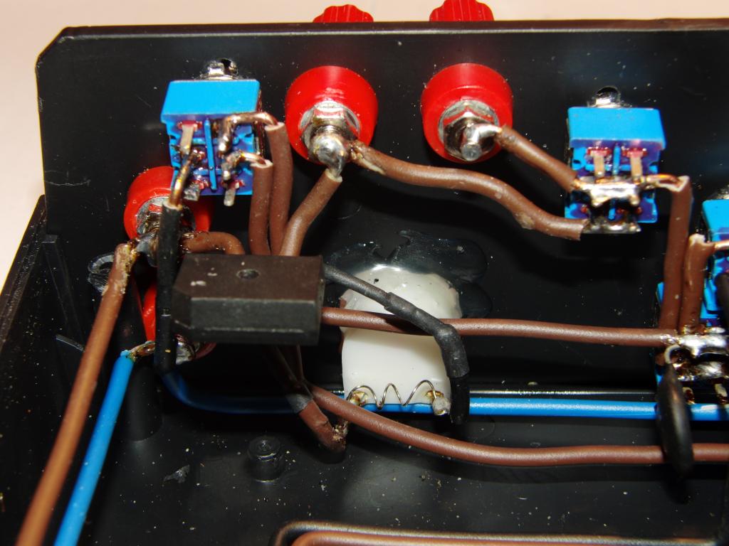
Schematics and truth table | 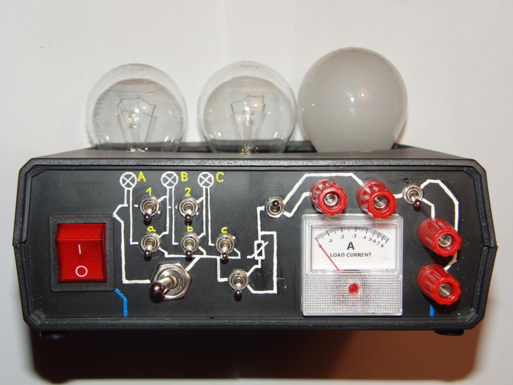 Front view | 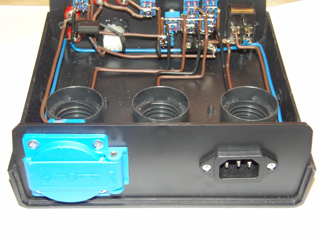 Back view | 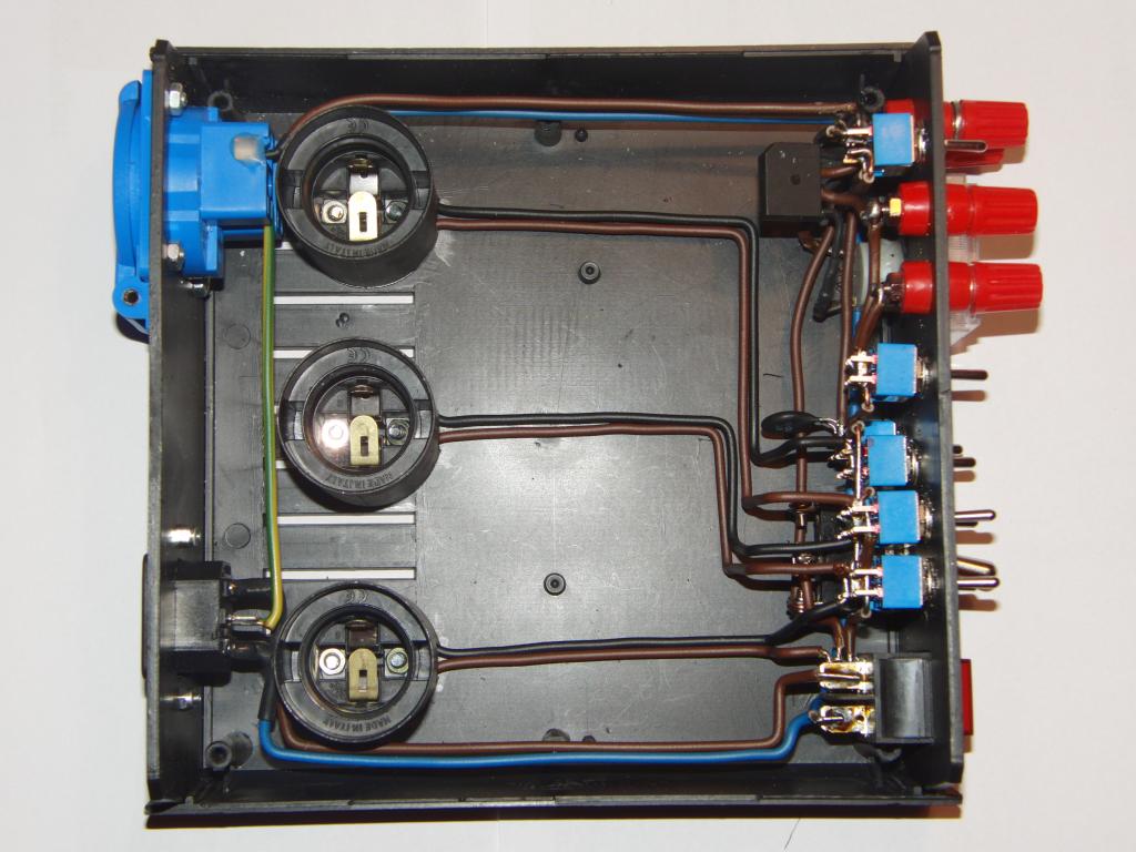 Inside view from top |
 Back side view | 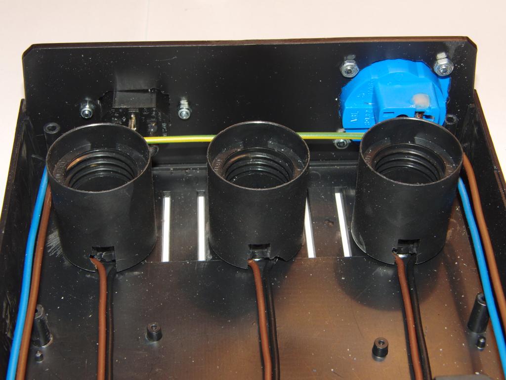 Back panel - front side | 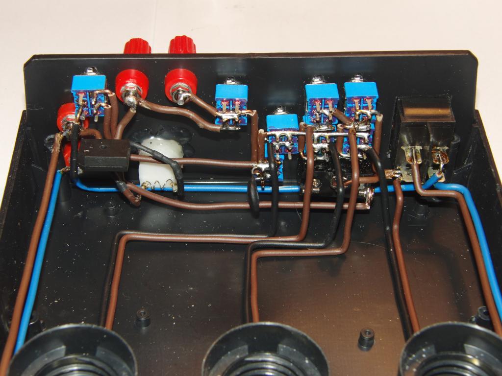 Front panel - back | 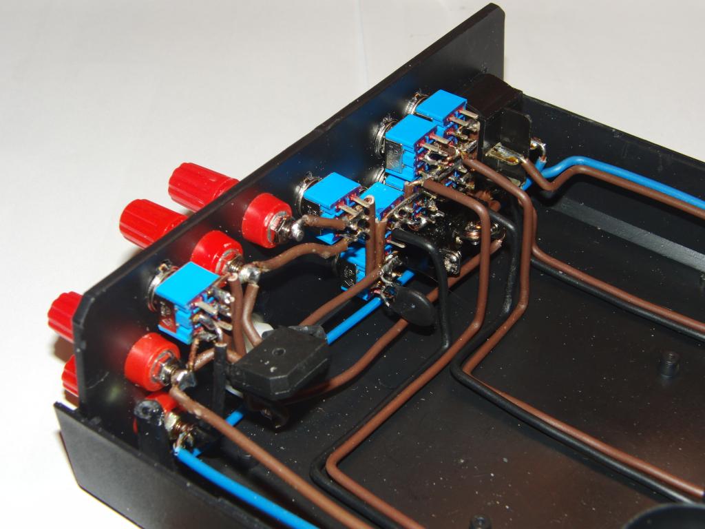 Front panel, back side view |
 Front panel - left back side | 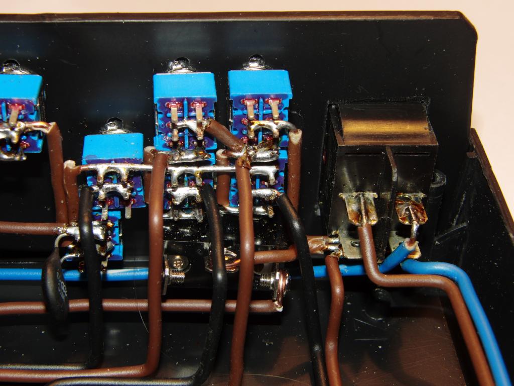 Front panel - right back side | 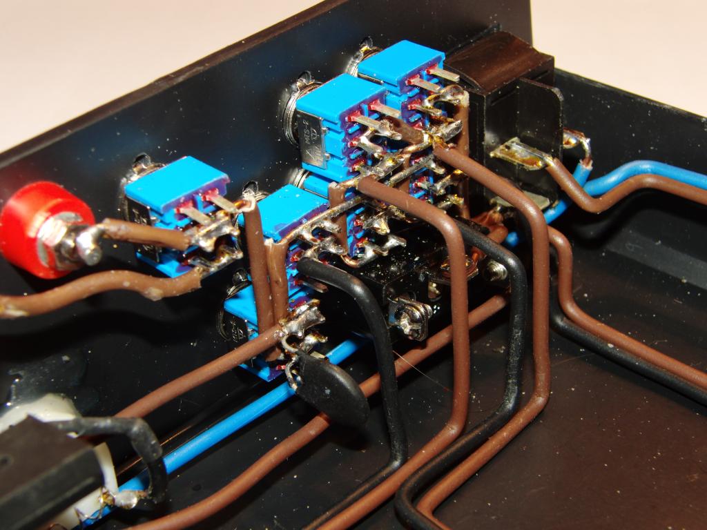 Front panel, right back side view | 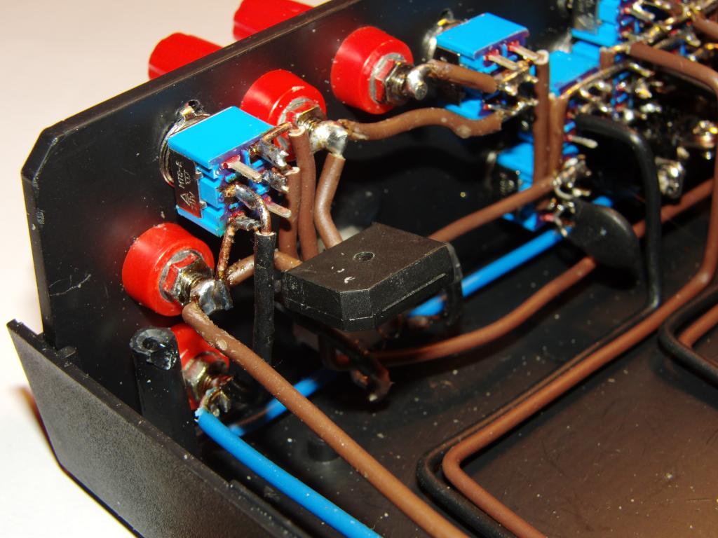 Front panel - left back view |
 Front panel, right back side | 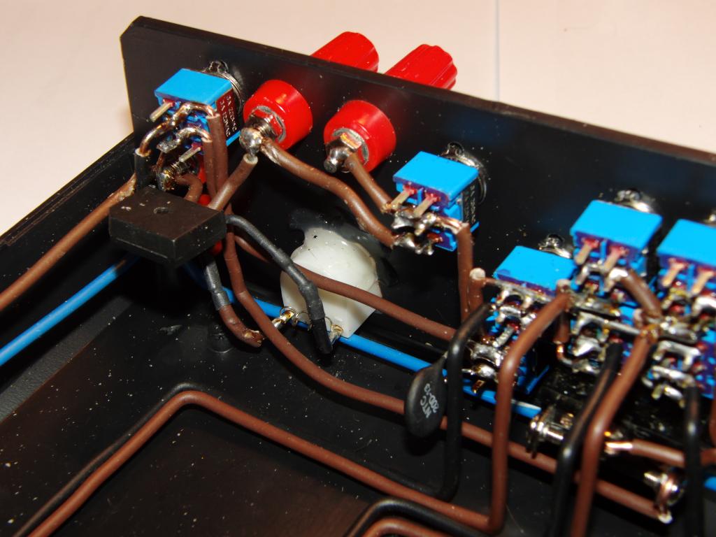 Front panel, left back side | 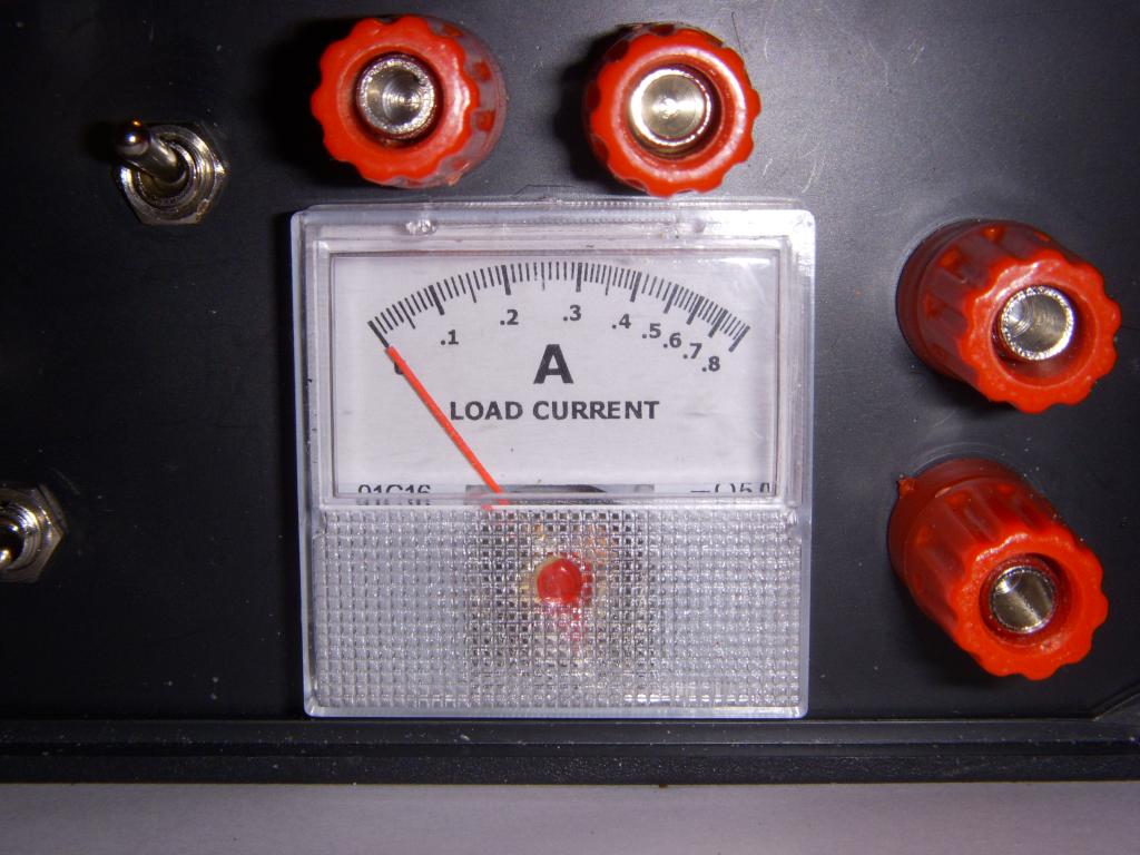 Ammeter dial | 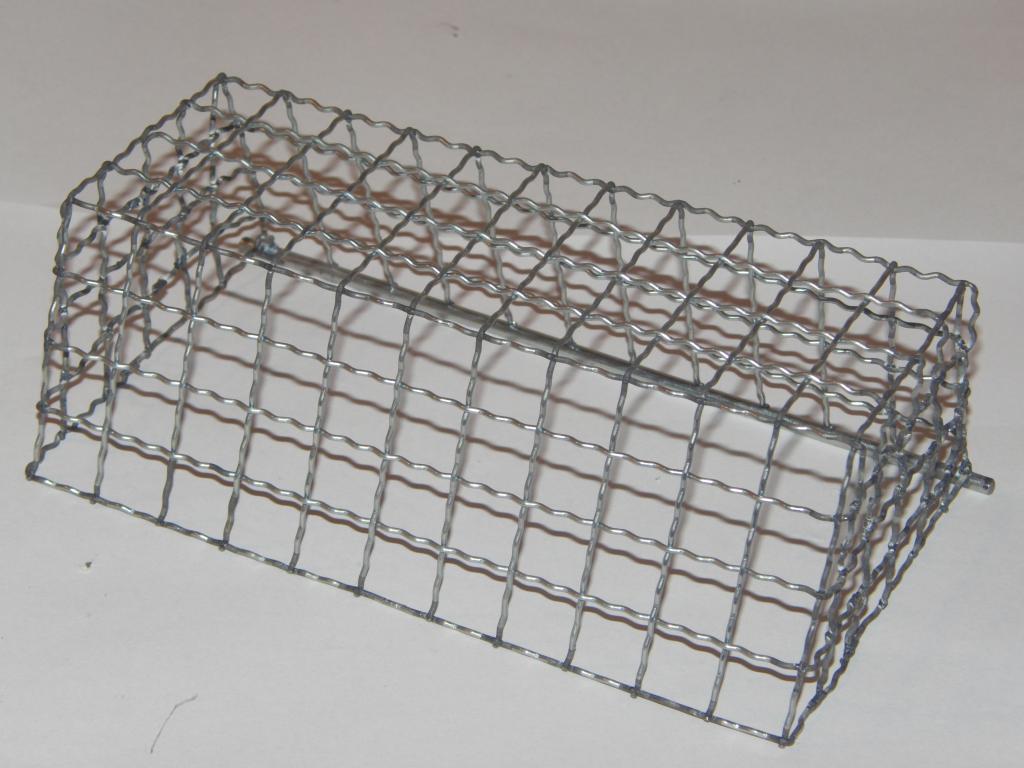 Bulb cage |
 Cage welds, right side | 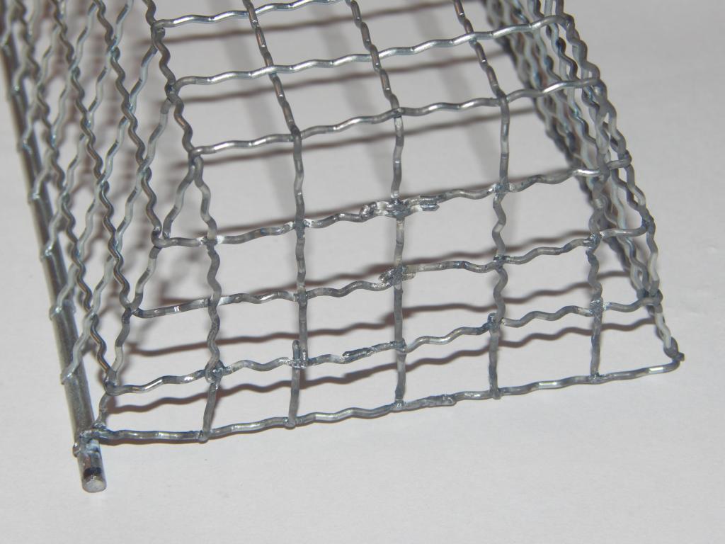 Cage welds, left side | 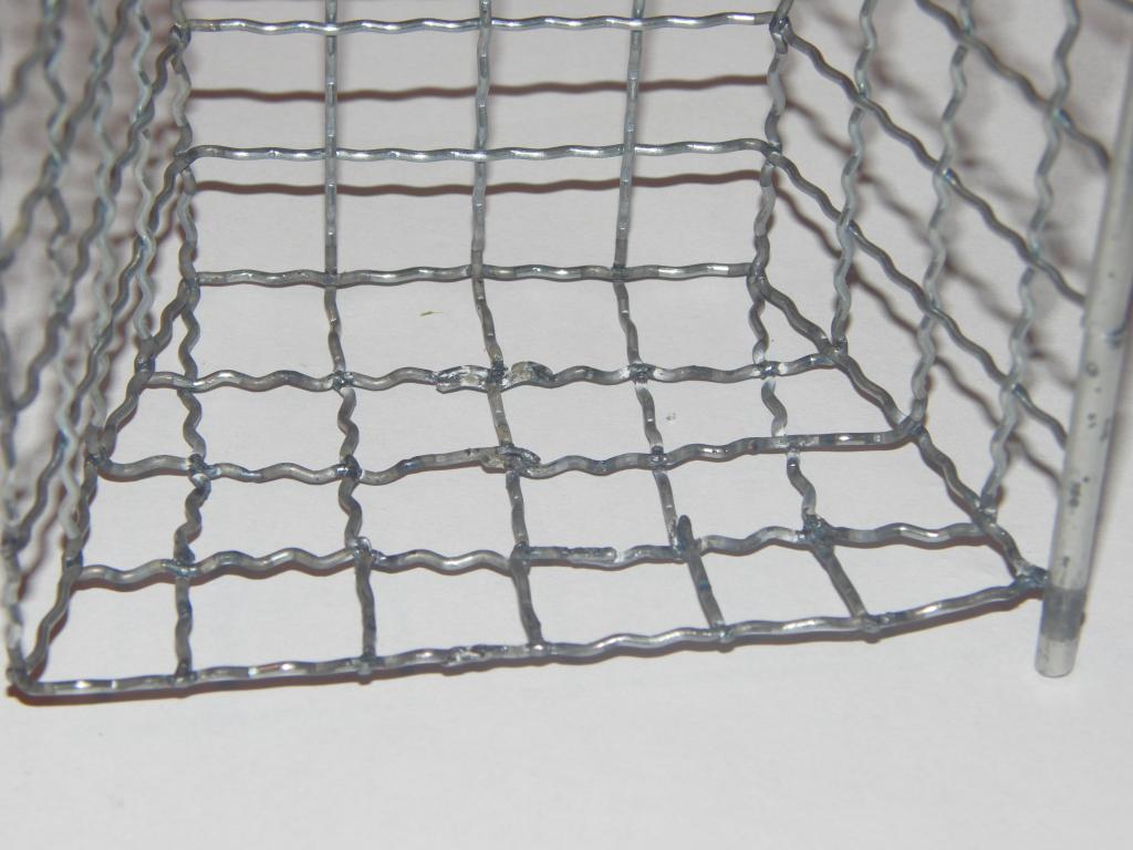 Cage welds, left inner side | 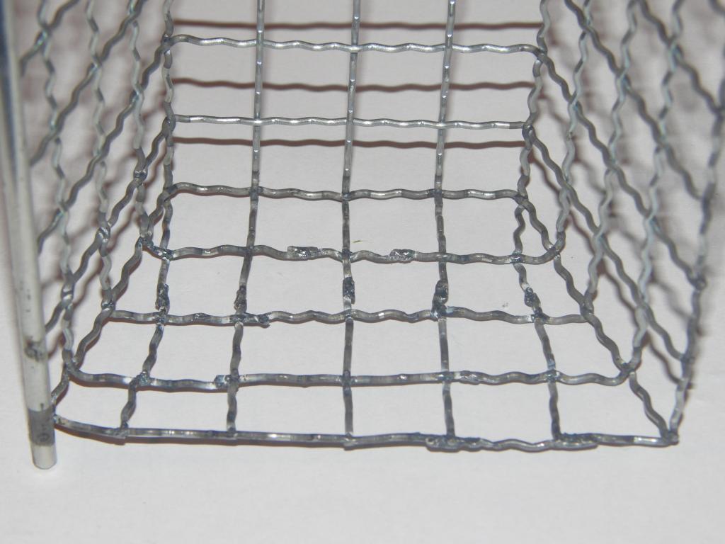 Cage welds, right inner side |
 Cage assembly | 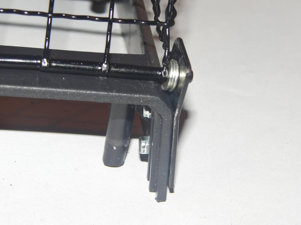 Cage hinge, inner side | 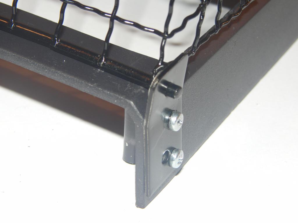 Cage hinge, outer side | 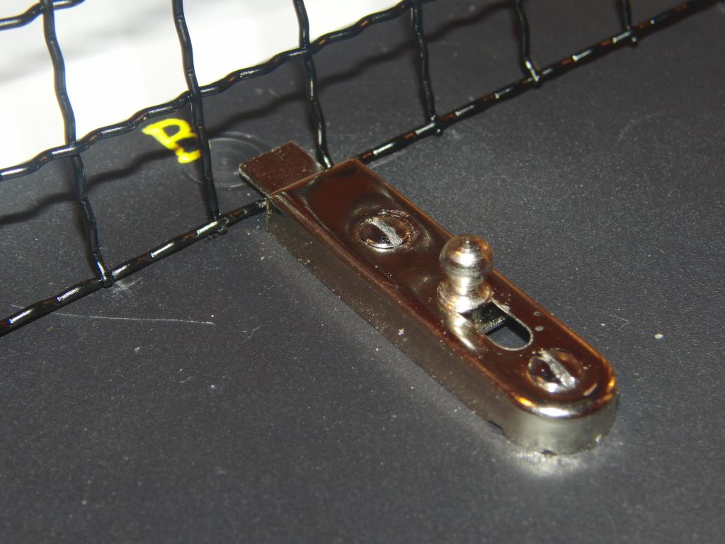 Cage latch |
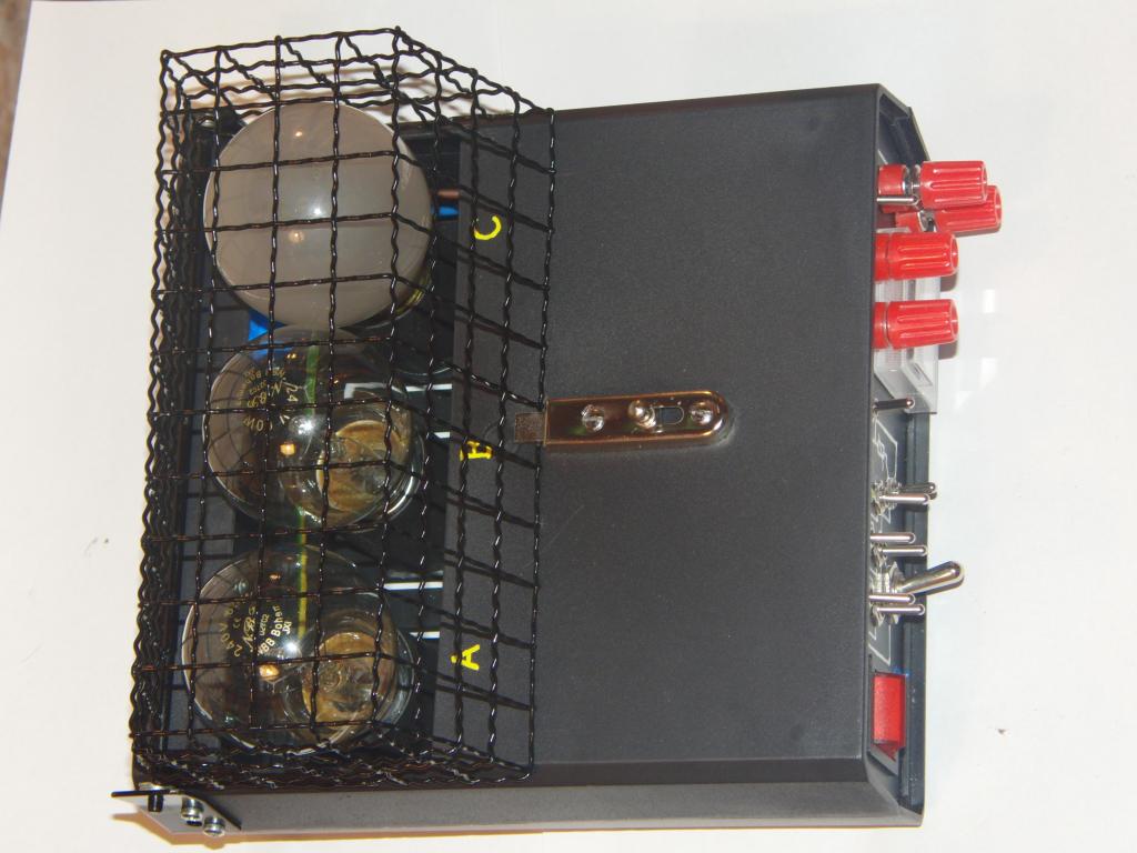 Top view | 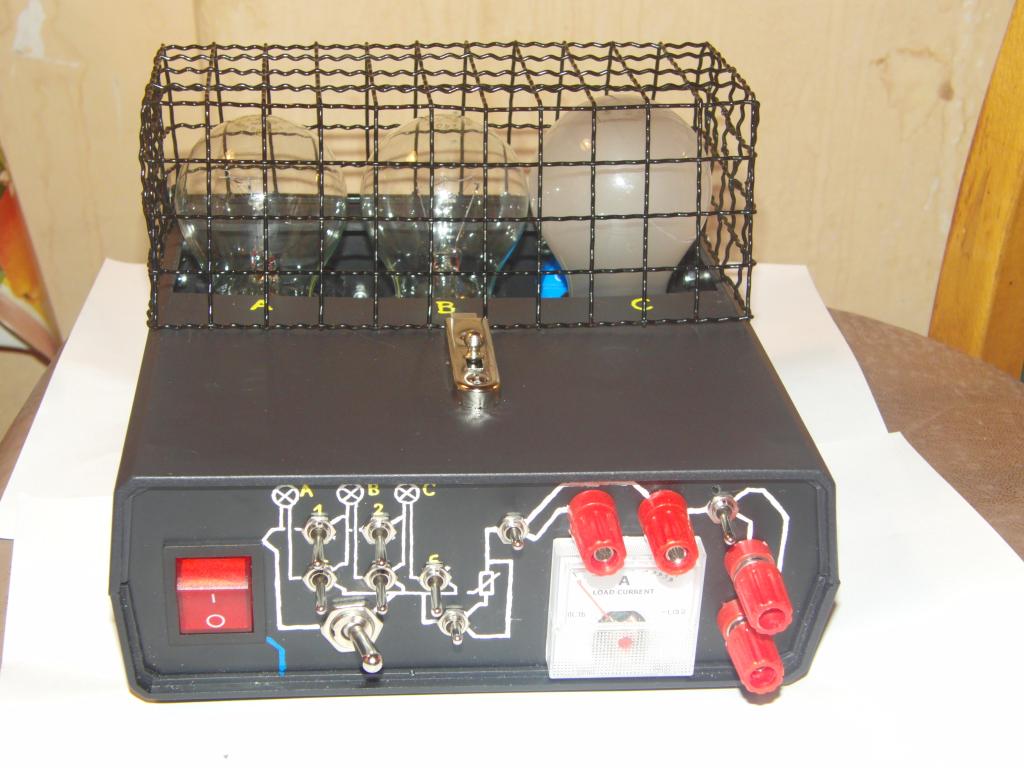 Front view | 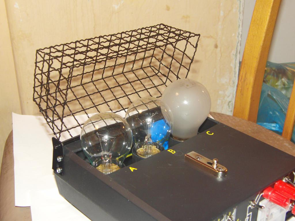 Open cage | 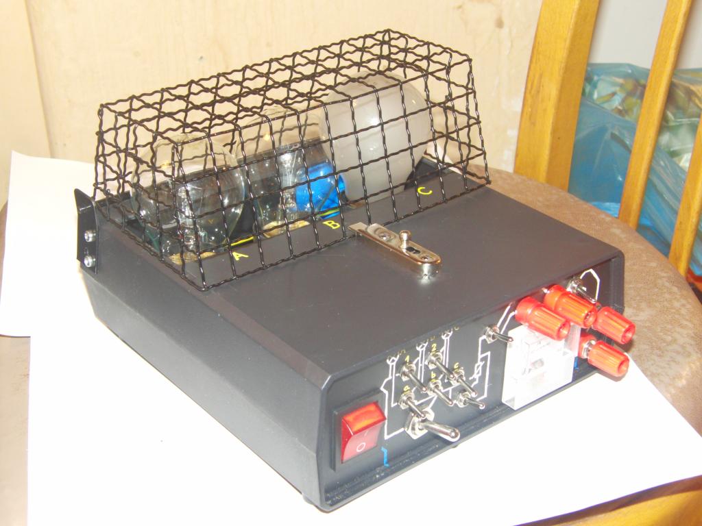 Closed cage |
 Limiter, top and front side | 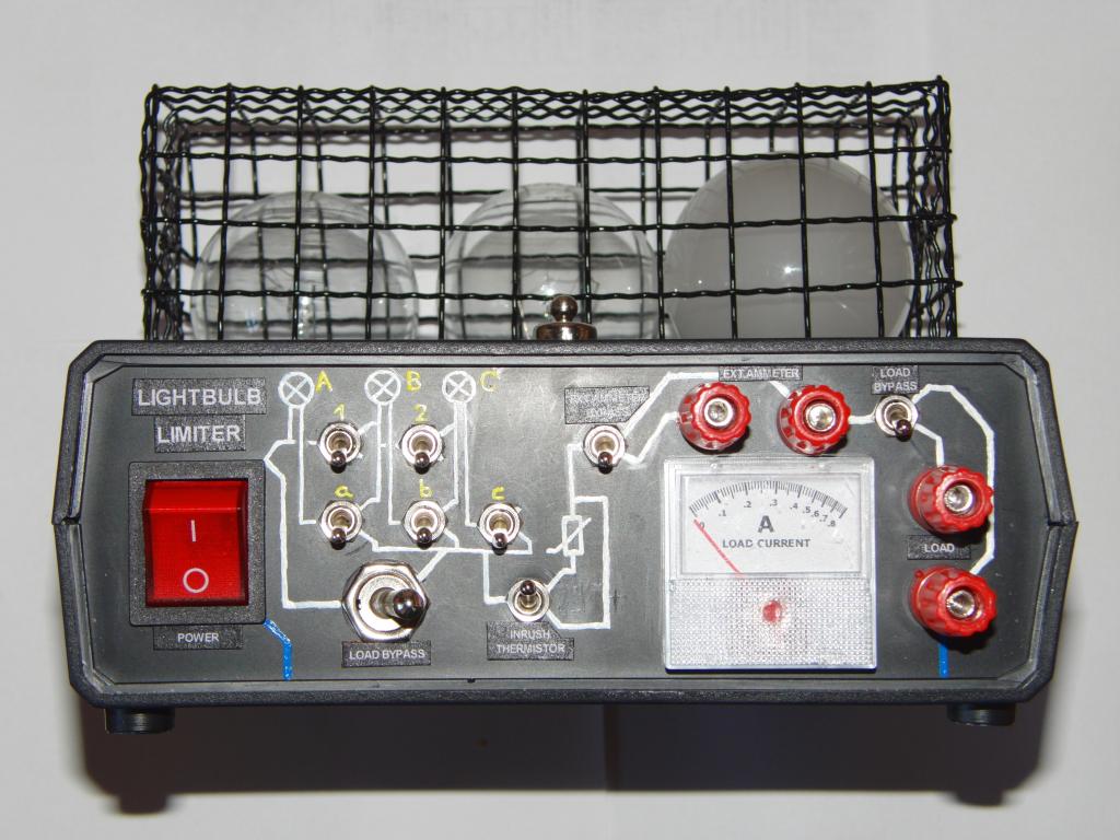 Limiter, front side with labels | 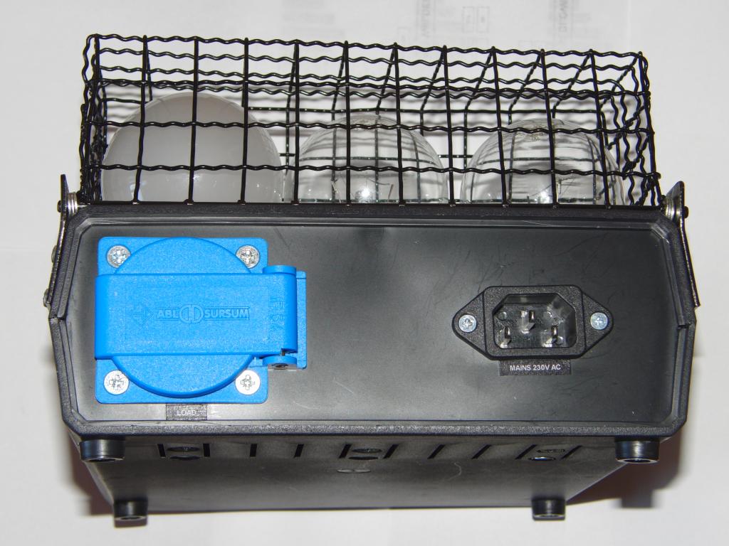 Limiter, back side |
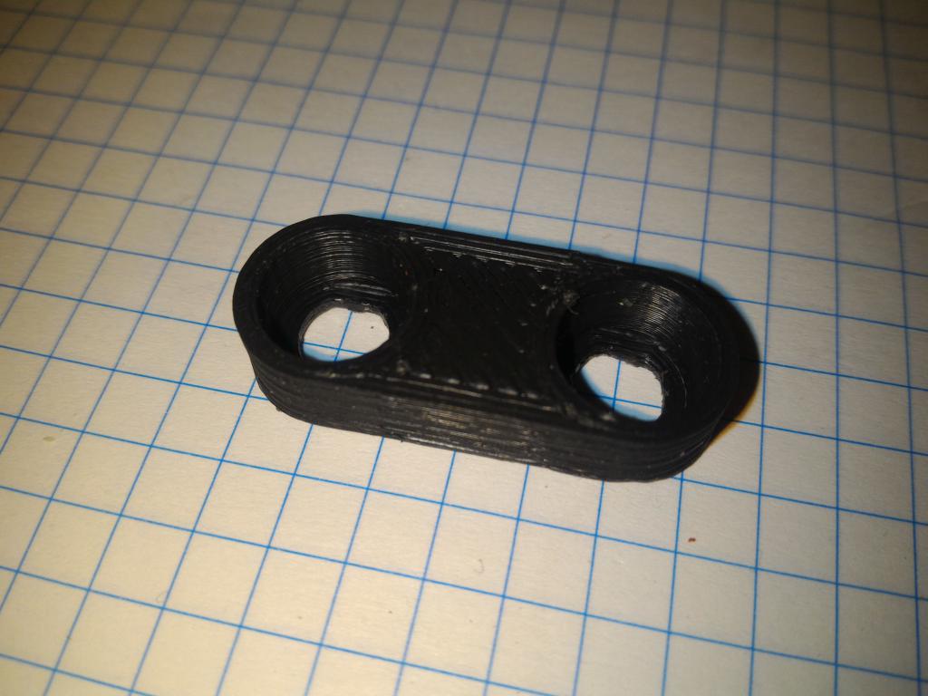
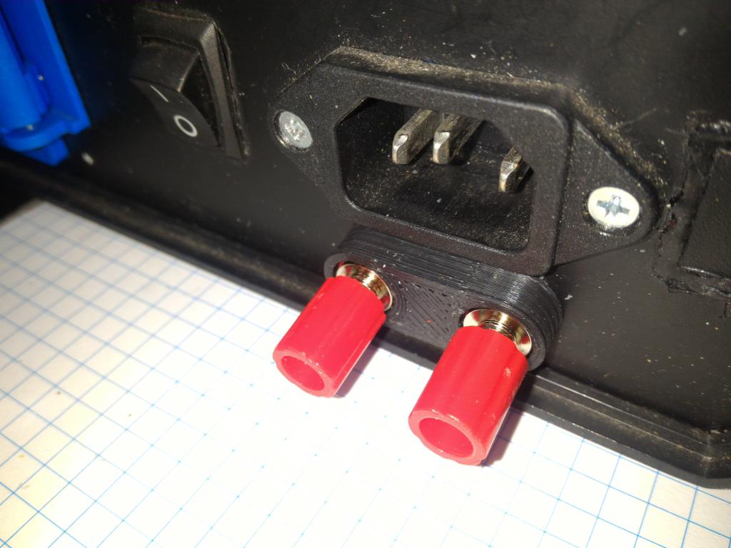
A pair of binding posts was added as an alternative power input. As the posts used have a metal rim exposed to touch, a housing/cover was 3d-printed. In addition, this housing also strengthens the rather flimsy binding posts against being broken off by careless handling of the device.
 Binding post cover | 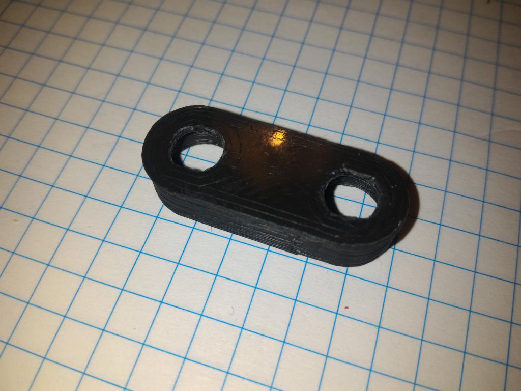 Binding post cover | 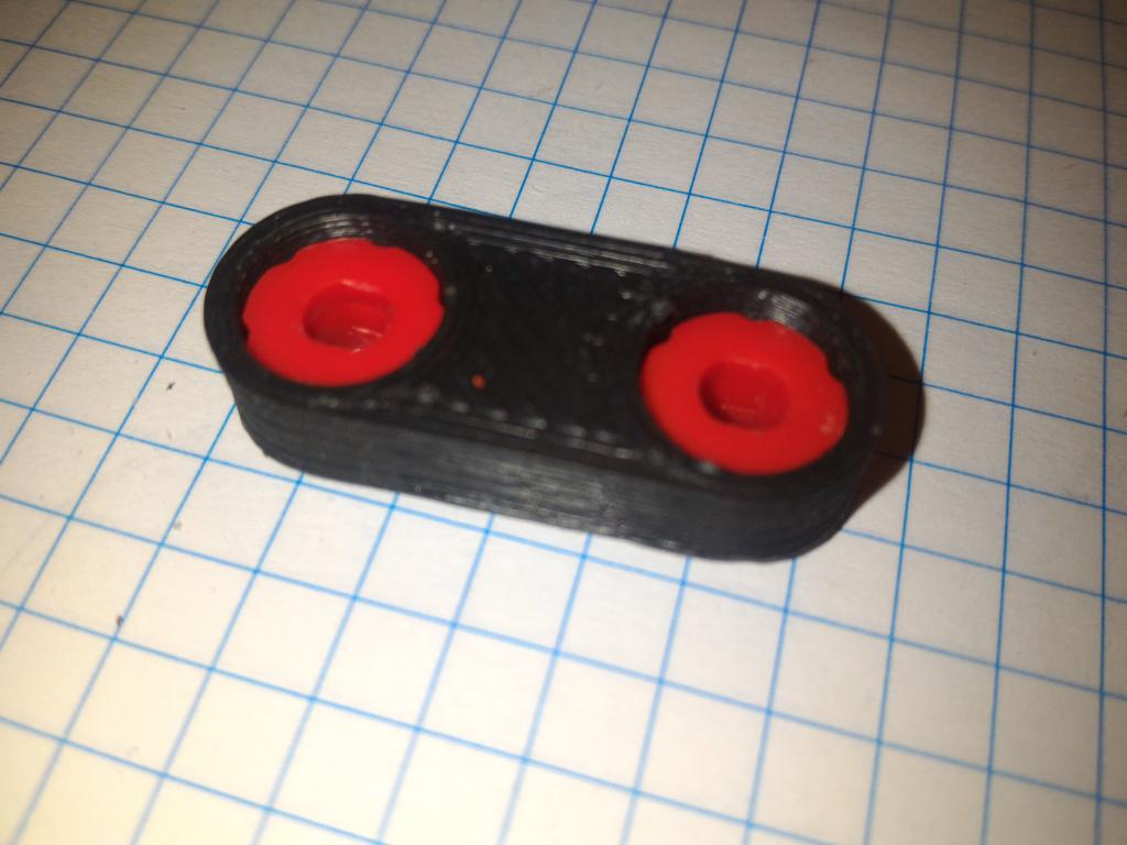 Cover with bottom parts | 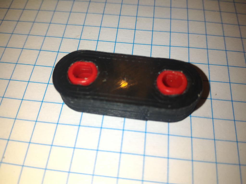 Cover with bottom parts |
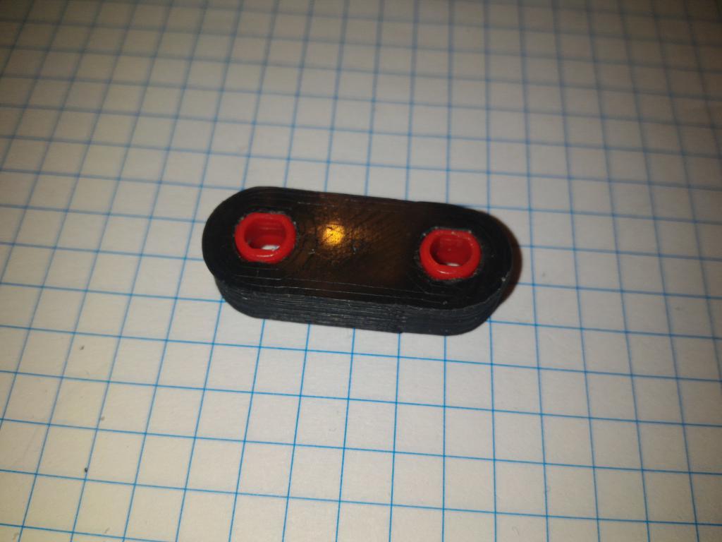 Cover with bottom parts | 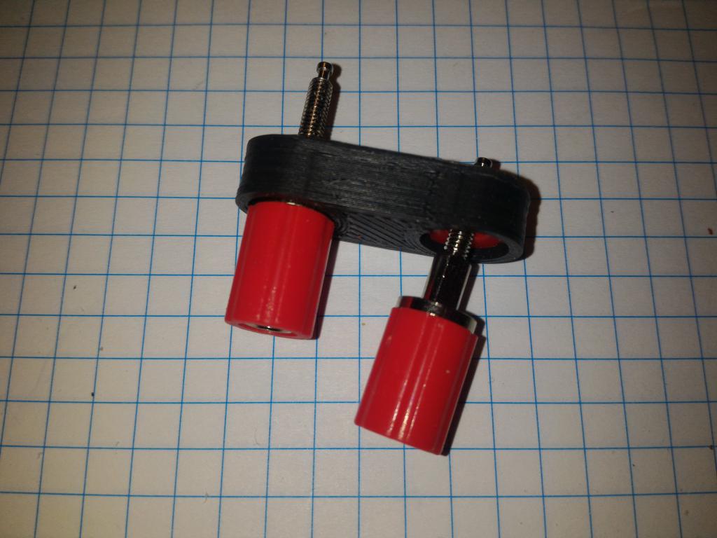 Posts in | 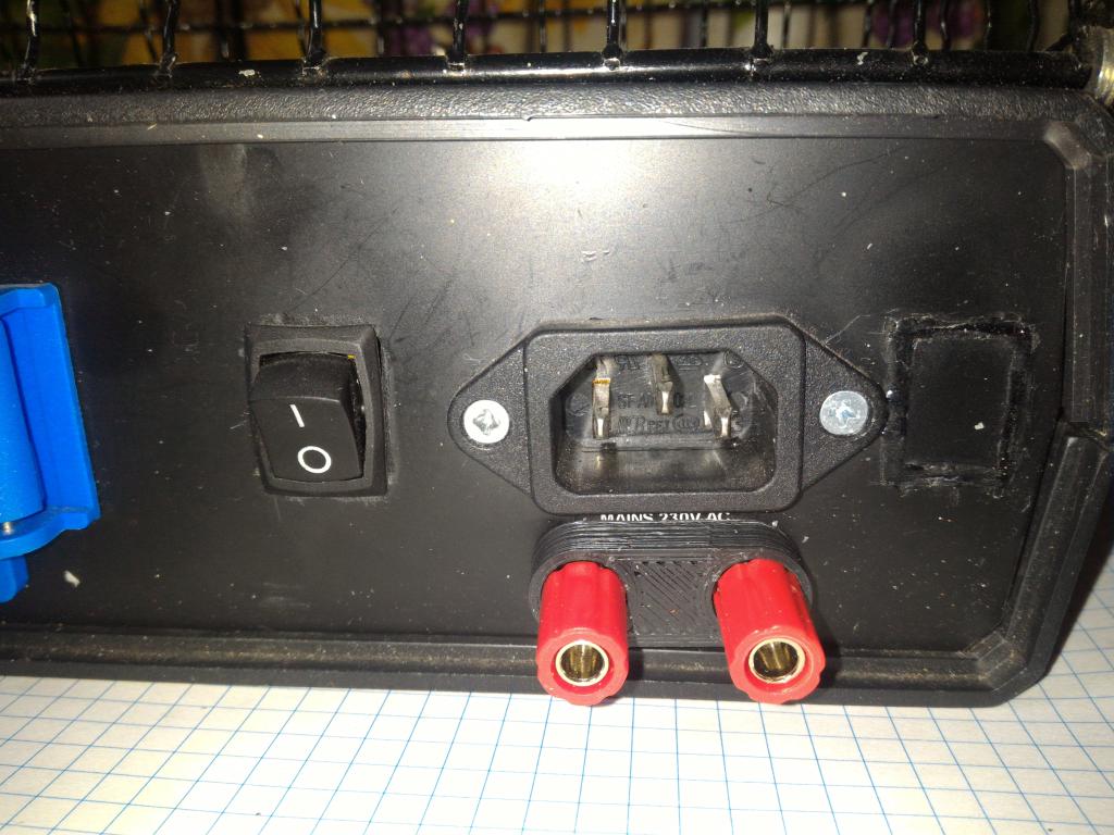 Power input posts | 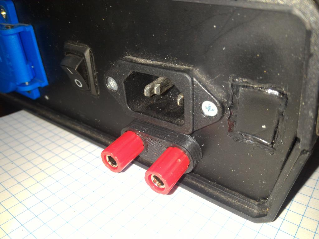 Power input posts |
 Power input posts | 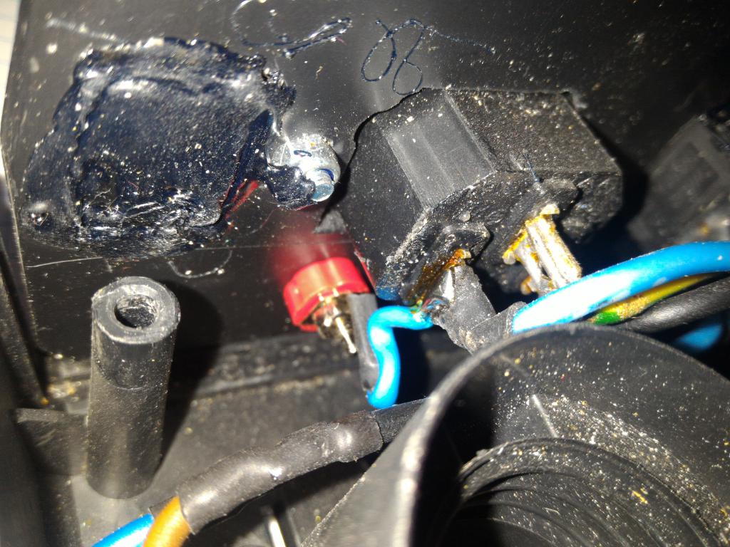 Power input posts, wiring | 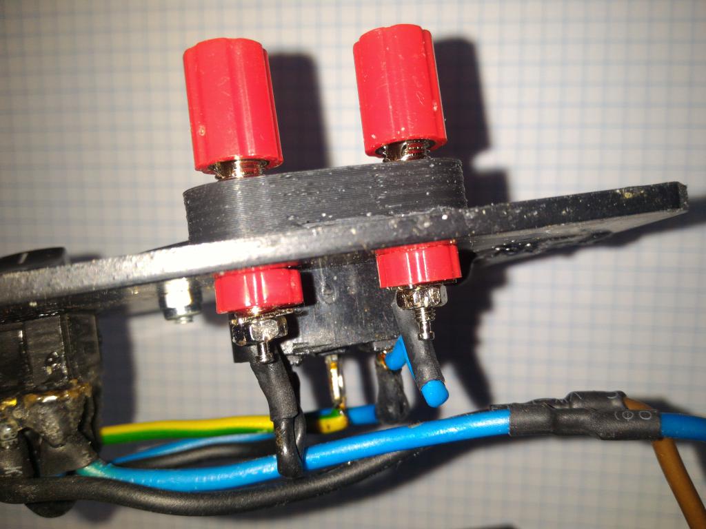 Power input posts, wiring | 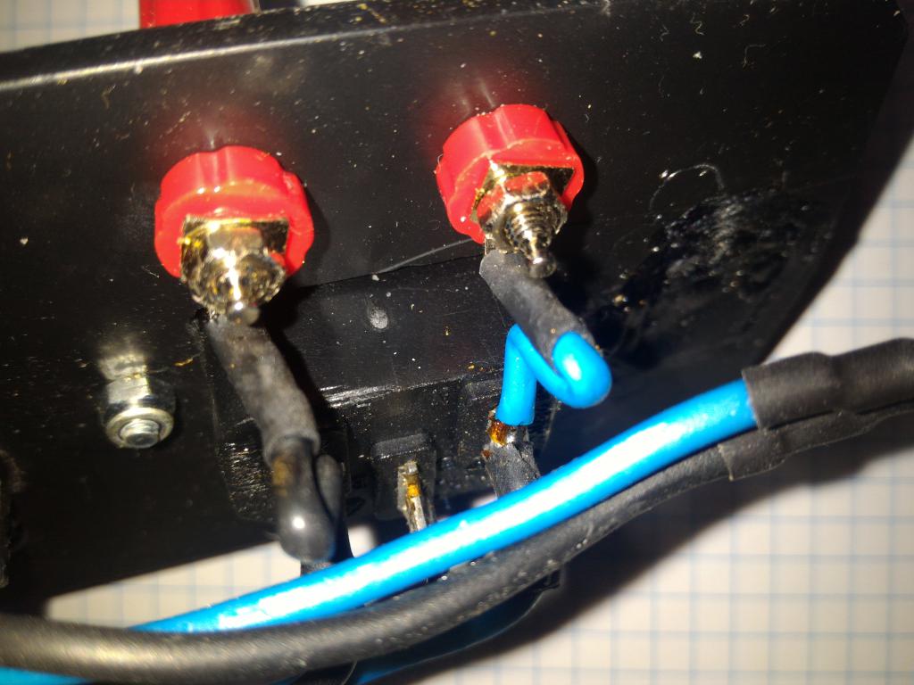 Power input posts, wiring |