 Why
WhyWhat
Design
Circuit
Modification of design
Bug and further mod
Connection box
Cutting holes
Lightbulb holder
Wiring
Final assembly and tests
Field deployment
Mods
Wire cage
Binding post covers
Caveats
Files
TODO
In many cases, a power-consuming device has to be protected against overcurrent;
alternatively, the current flow has to be stabilized on certain reasonable value.
Lightbulbs have a heated filament.
In other cases, it is necessary to sink a significant amount of electrical power. A resistive load that transfers the electricity into waste heat is then desired.
And sometimes the powers necessary to be handled aren't just few dozen to hundred watts anymore - kilowatt range of power is needed.
Lightbulbs are especially suitable for current limiting; the filament, when cold, can be over ten times less resistive than when hot. When more current is forced through the filament connected in series with a load, it heats up, its resistance increases, and it takes progressively higher share of voltage, lowering the voltage across the load, until a steady state is reached.
A Lightbulb Limiter was already built earlier, based on
the E27 socket lightbulbs. This is however suitable only for low power
operations; the available lightbulbs aren't exactly powerful.
was already built earlier, based on
the E27 socket lightbulbs. This is however suitable only for low power
operations; the available lightbulbs aren't exactly powerful.
Luckily, higher-power lamps are available. The cheapest ones at hundred watt to kilowatt
range are the R7S linear halogen lamps. It was decided
to build the device around these lamps. They come in several standard lengths corresponding
to the lamp's power; in a rough ballpark, 78mm for lowest powers, 118mm for 120-500 watts,
189mm for 1000 watts, 254mm for 1500 watts, 331mm for yet higher powers.
Support for 118 and 189 mm lamps was chosen, allowing configuration ranging between 3x100W to 3x1000W. Typically the lamps used will be 2x500+1x1000W, or 230+500+1000W.
An IEC 60320 C14 power socket was chosen as input due to easy availability of the corresponding
power cables. It is rated only for 10 amps, but the load at 3 kW is about 13 amps, which may be acceptable
for shorter period. A pair of 19mm-spaced binding posts was also added.
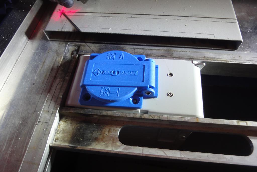
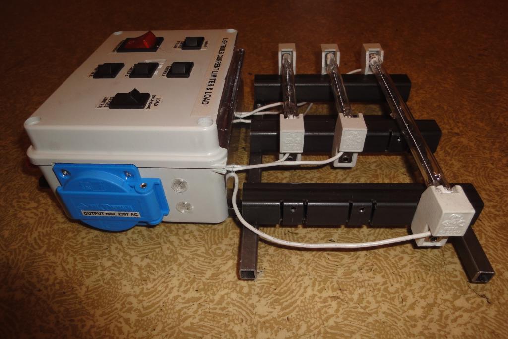
For the output, a lidded CE 7/5
socket, with the left pin designated as L and right as N, was chosen. A pair of binding posts was
added as well, to facilitate attachment of unexpected devices.
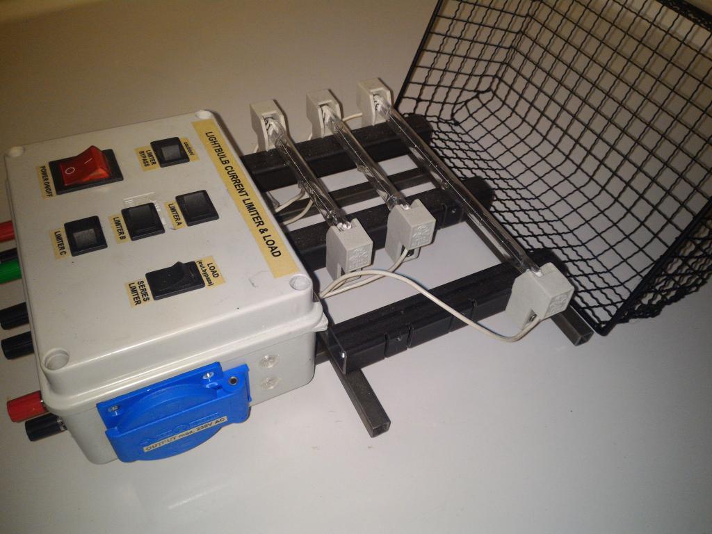
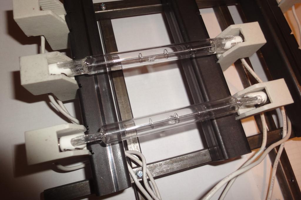
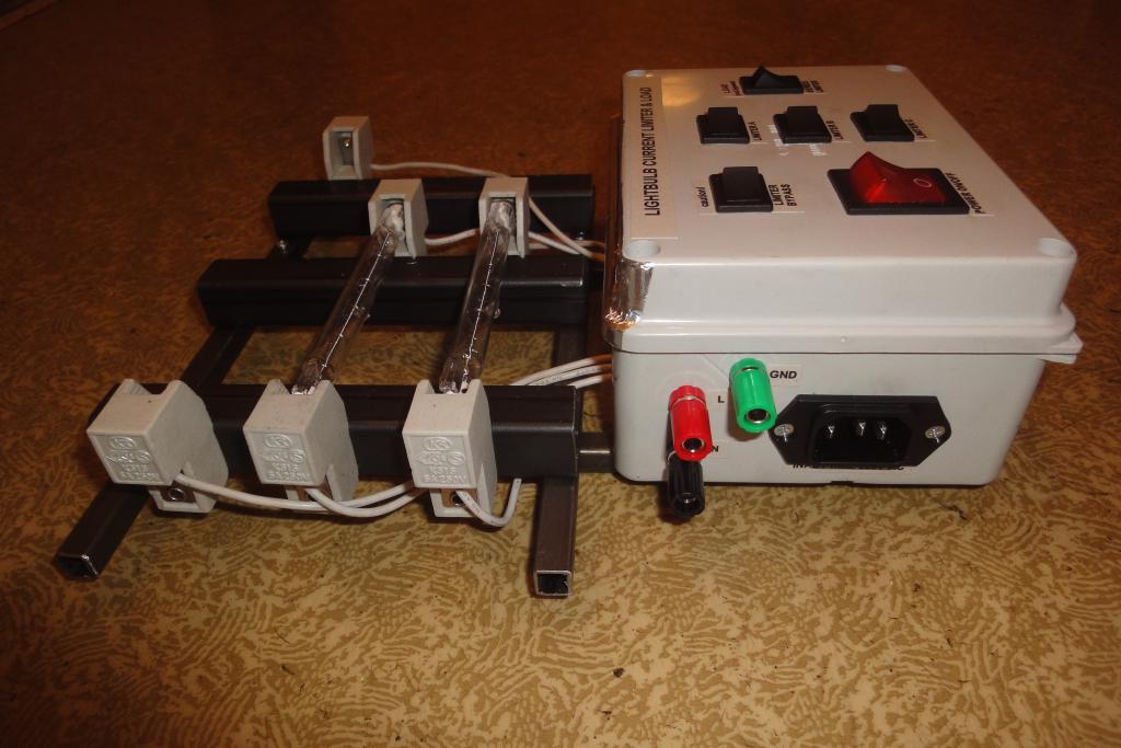
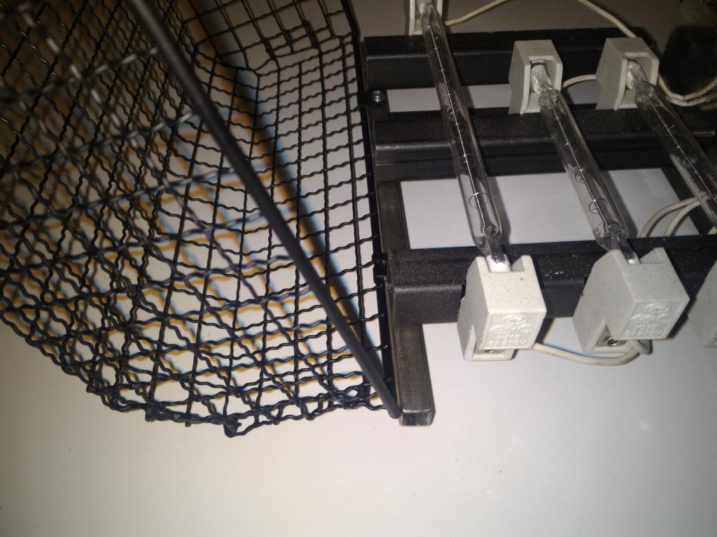
The R7s sockets are mounted on a custom-made steel holder, with option to configure each position for either 118 or 189mm length.
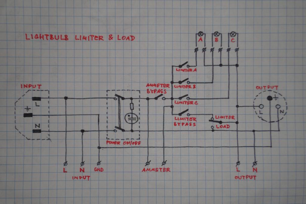
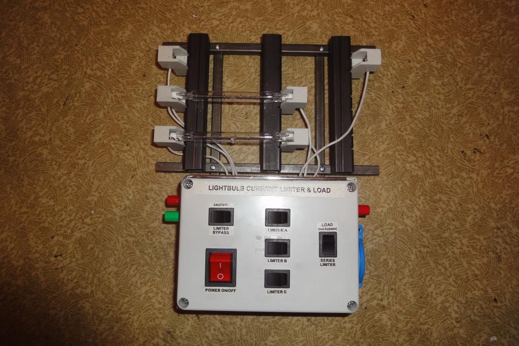
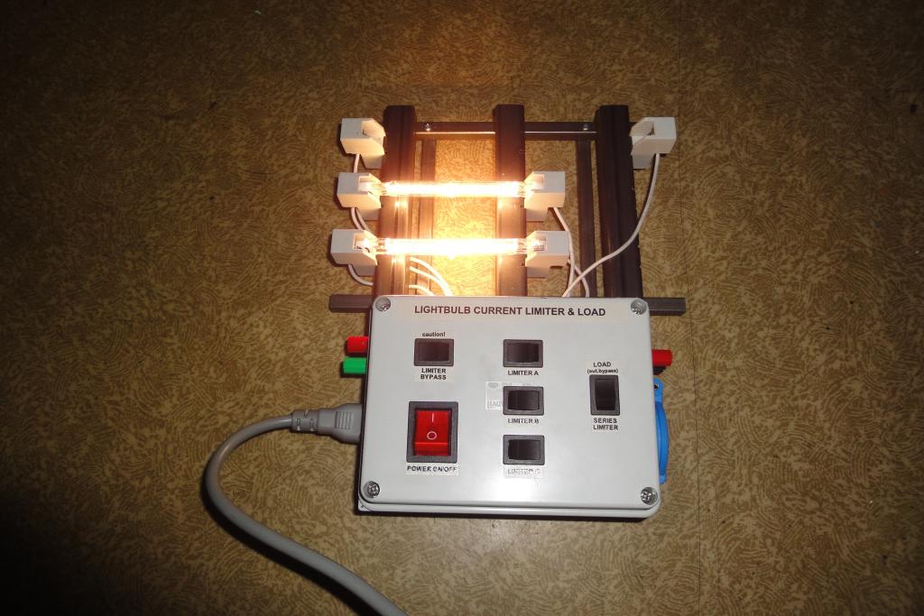
The main power switch, the switches for enabling the individual lamps (all connected in parallel), the lamps bypass switch and the selector between acting as a series limiter or a resistive load are mounted on the lid.
The lamp bypass switch is interlocked with the load/limiter selector to not allow lamp bypassing into load function, which would equal a hard short of the input.
The design was field-tested. The original positions of the binding posts were found to be wrong, as they were poorly accessible. There was also missing attachment for an ammeter, which turned out to be sorely needed.
The binding posts were moved to the front panel. Another pair of the posts was added, together with a bypass switch, to facilitate attaching an optional ammeter.
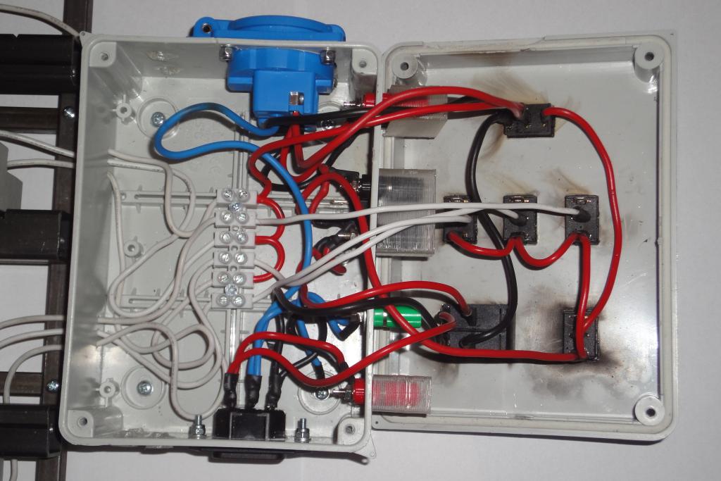
The holes were cut into the panel without fully stripping the box, using aluminium foil stuffed into the box as protection against the beam. The beam however still managed to scorch a few wires, but the damage on the insulation was not full-thickness and was judged just superficial.
Holes for the original binding post positions were covered with custom-made 3d-printed plugs.
A bug was discovered during documenting. The added ammeter connection would not function in load mode, the terminals would be shortcircuited. The ammeter posts will have to be rewired.
The schematics are ugly and are scheduled for being redrawn properly.
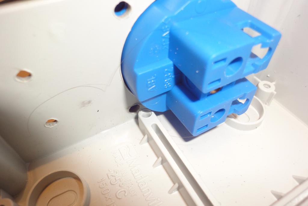
An electrical installation case was chosen for the user interface housing. The Marlanvil 008.PL box was chosen on the basis of availability and suitable size, 150x110x70 mm.
The material is an electrical-grade ABS.
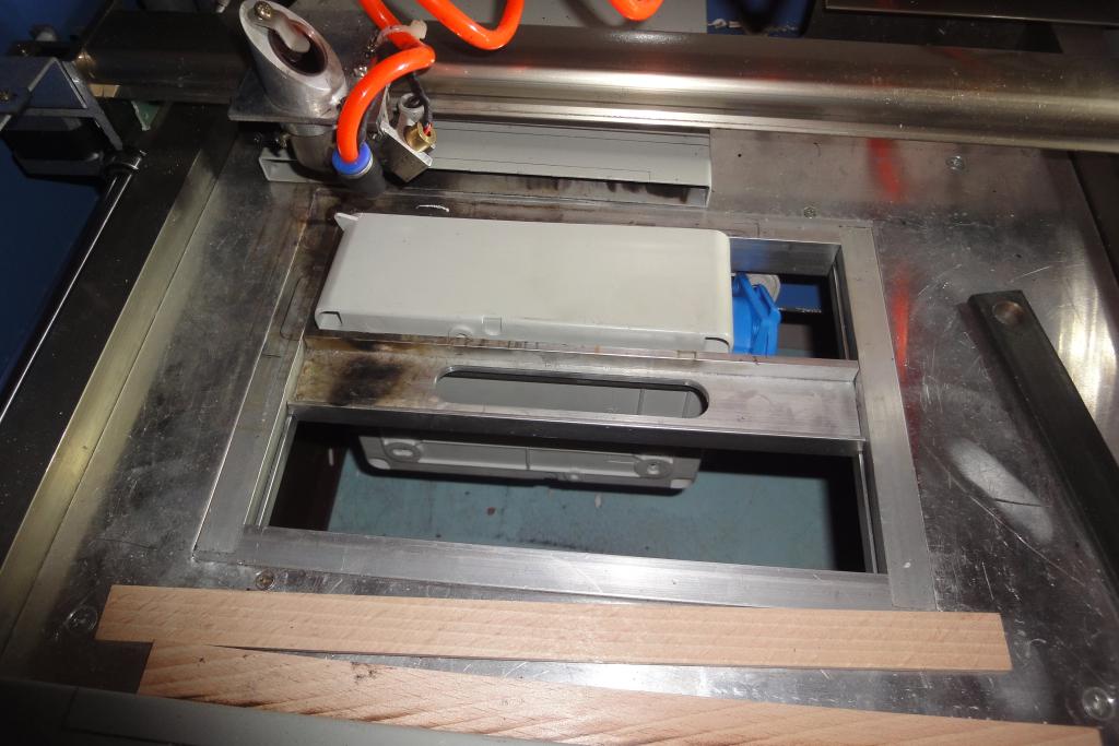
The holes on the top and side panels were drawn in OpenSCAD, exported to DXF, and
cut on the laser cutter. The laser cutter was modded earlier by grinding out a large hole
in the bottom to allow insertion of taller objects. This allowed insertion of the entire box
bottom, so the sides can be cut. The cutting required several passes, at higher speed (12-15cm/s)
and lower current (8mA) to reduce overheating of kerf sides and the corresponding widening
and spreading of its edges.
The material produces vapors when cut, which tend to get ignited and produce copious amounts of soot. The flame extinguishes immediately after cessation of the beam. The soot tends to soak into the surface of the plastic and stay there and be difficult to remove.
The laser cutter has tendency to sometimes run the laser and move over the bed diagonally, then grind against the stops. This can damage the workpiece when not avoided and not caught on time.
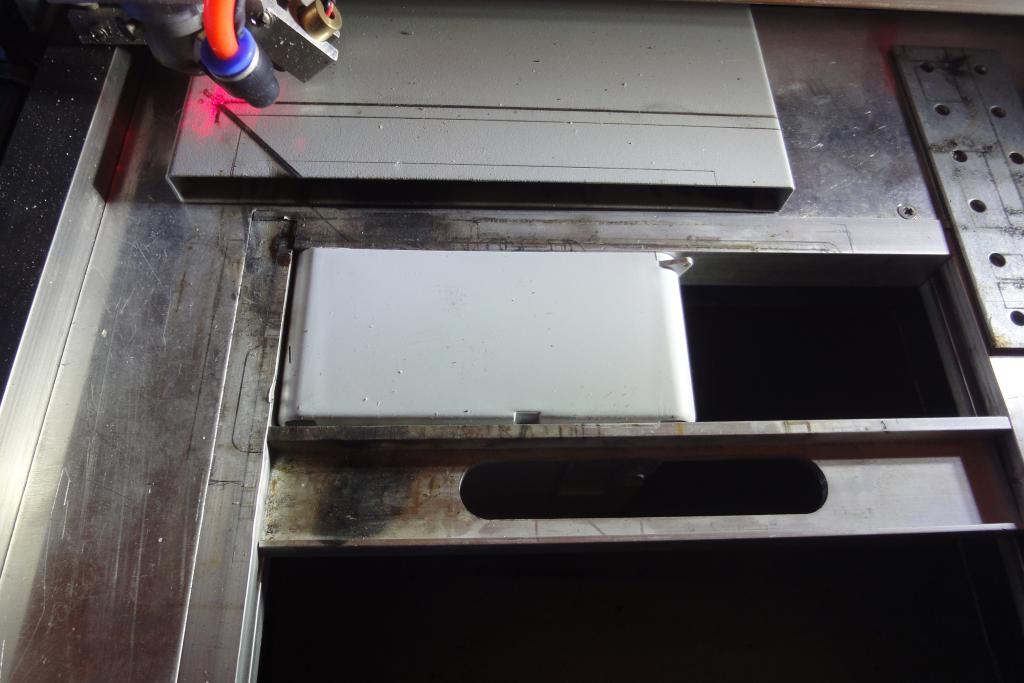 Lasercutting input side | 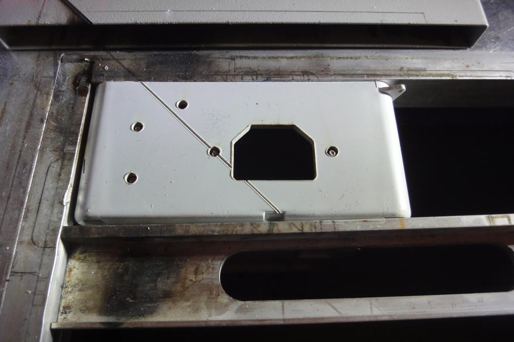 Lasercutting input side, showing diagonal line damage | 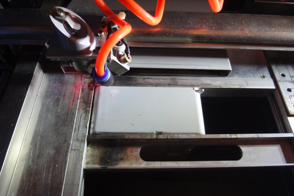 Lasercutting output side | 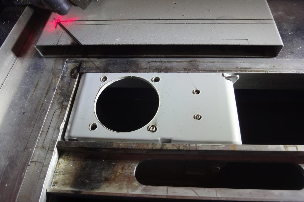 Lasercutting output side |
 Lasercutting output side | 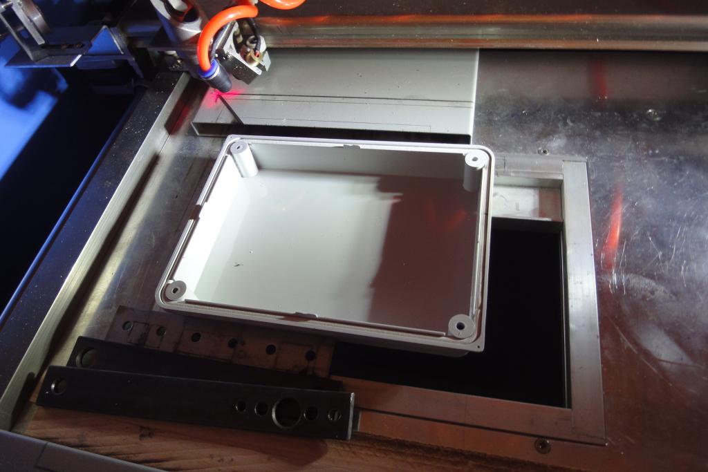 Lasercutting lid | 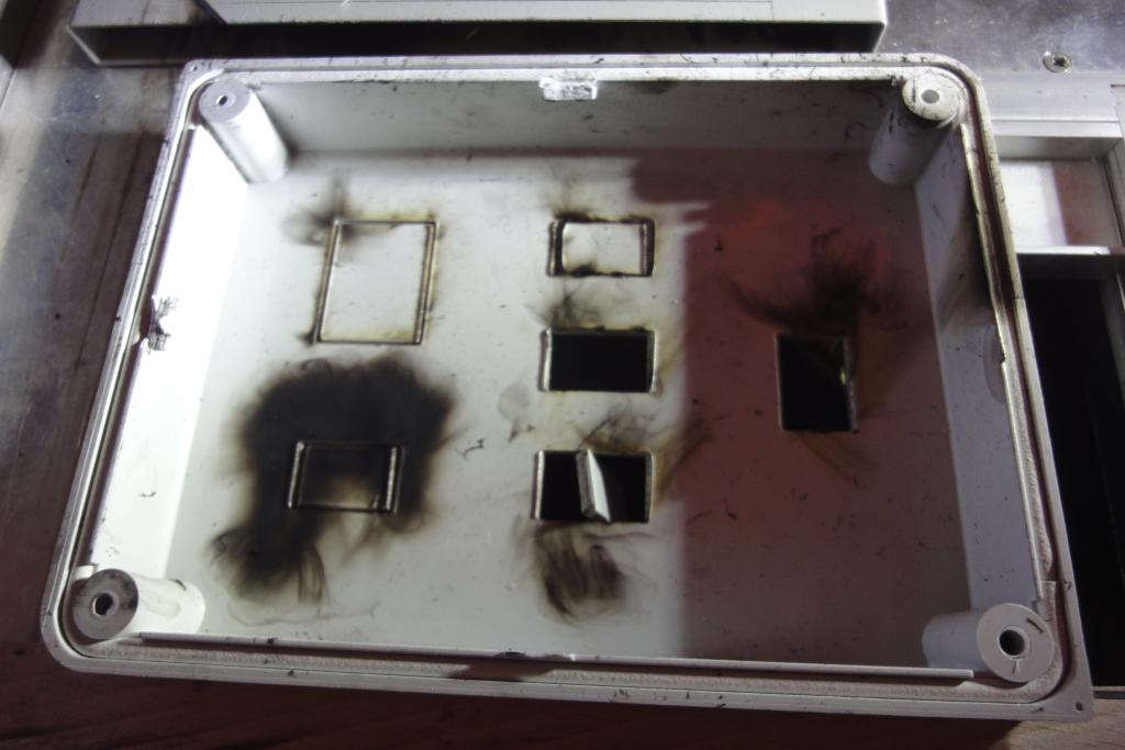 Lasercutting lid | 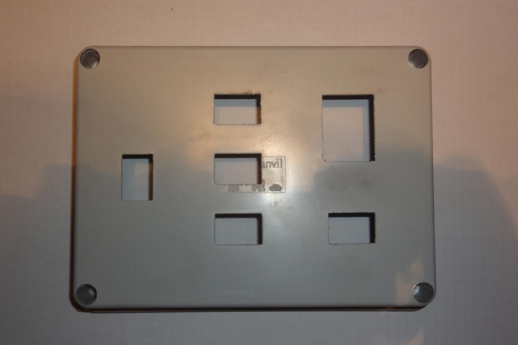 Lasercutting lid |
The position of the output socket was a little high, interfering with the lid. Two millimeters of the lid were manually ground away using a handheld Dremel mill. A little piece of reinforcing/mount bar on the bottom had to be ground away to provide space for socket mounting nut.
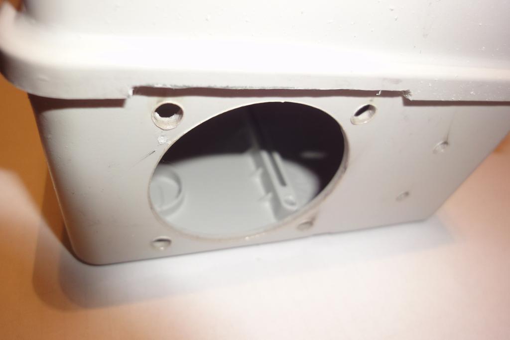 Output side lid cut | 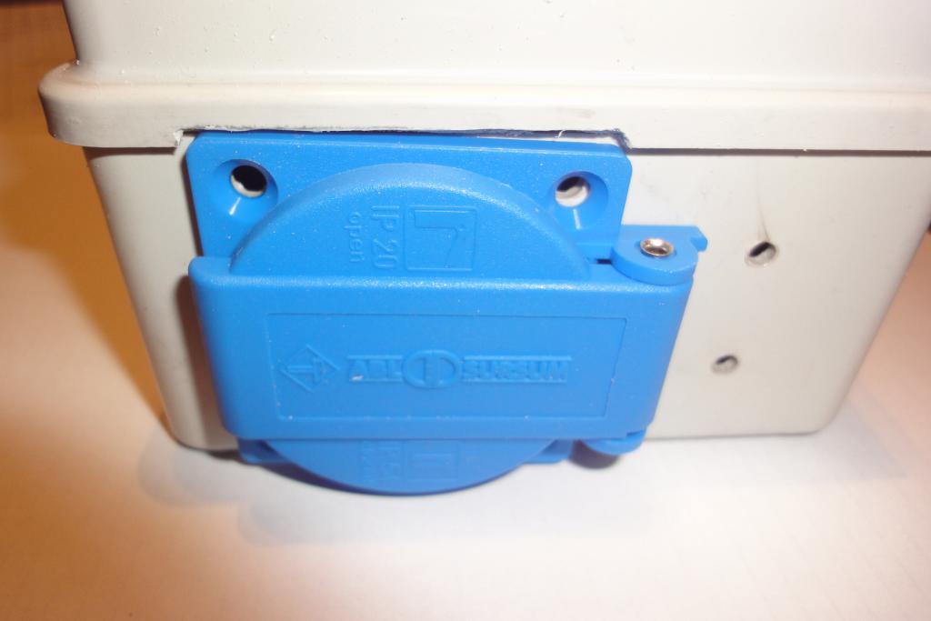 Output side lid cut | 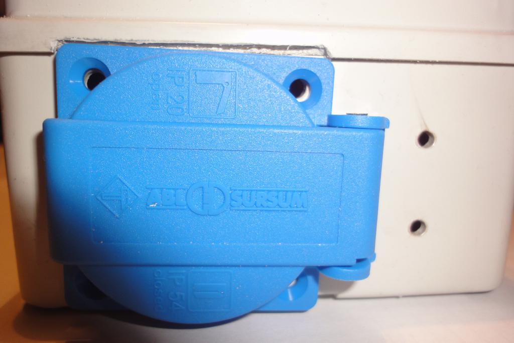 Output side lid cut |
 Output socket | 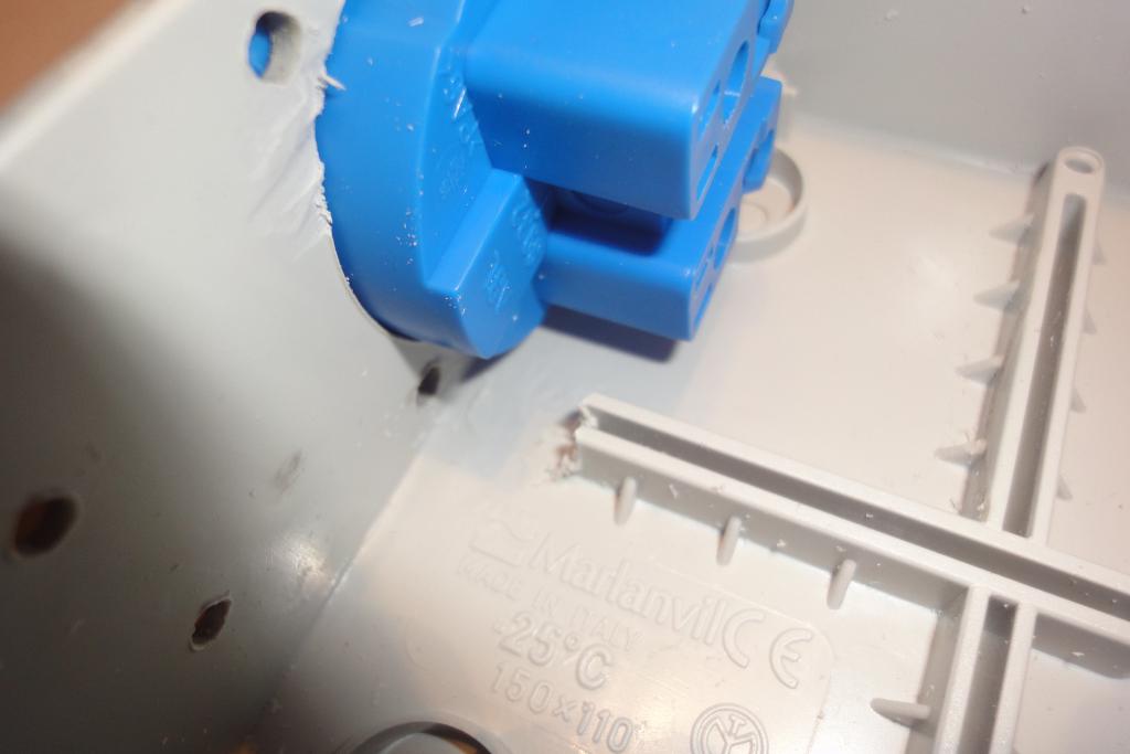 Output socket | 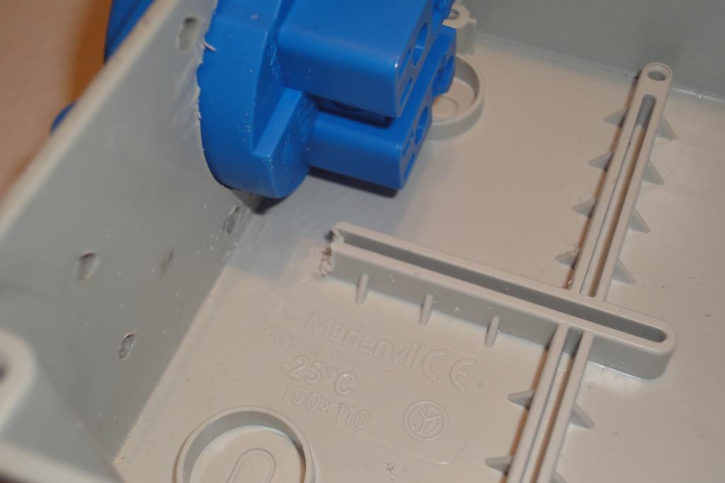 Output socket |
Modifications were needed to be made; they were performed on an assembled box.
 Lasercutting front panel mod | 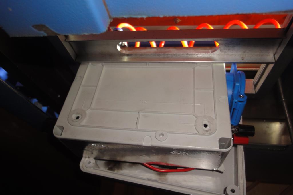 Lasercutting front panel mod, clamp view from bottom | 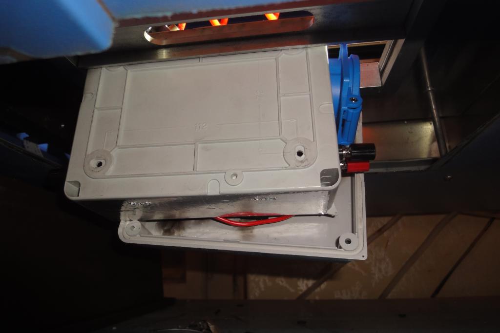 Lasercutting front panel mod, clamp view from bottom | 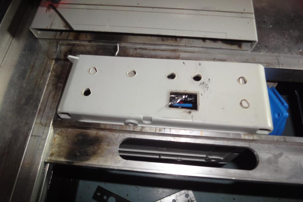 Lasercutting front panel mod |
The laser caused some superficial damage on the wires.
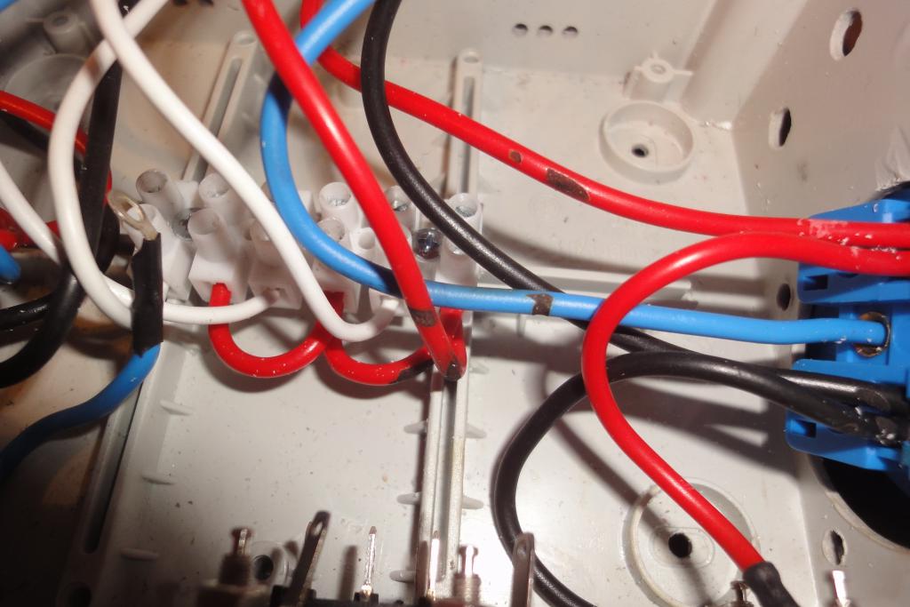 Laser scorch marks |
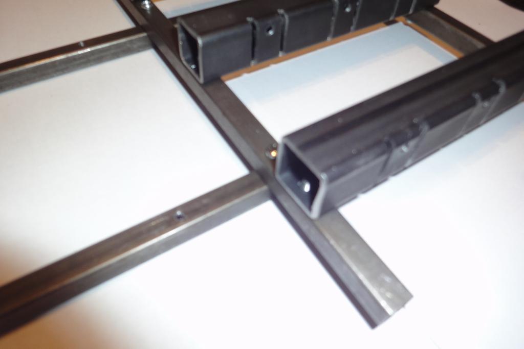
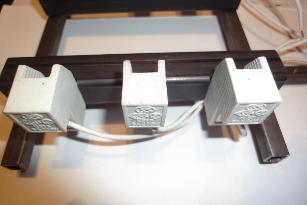
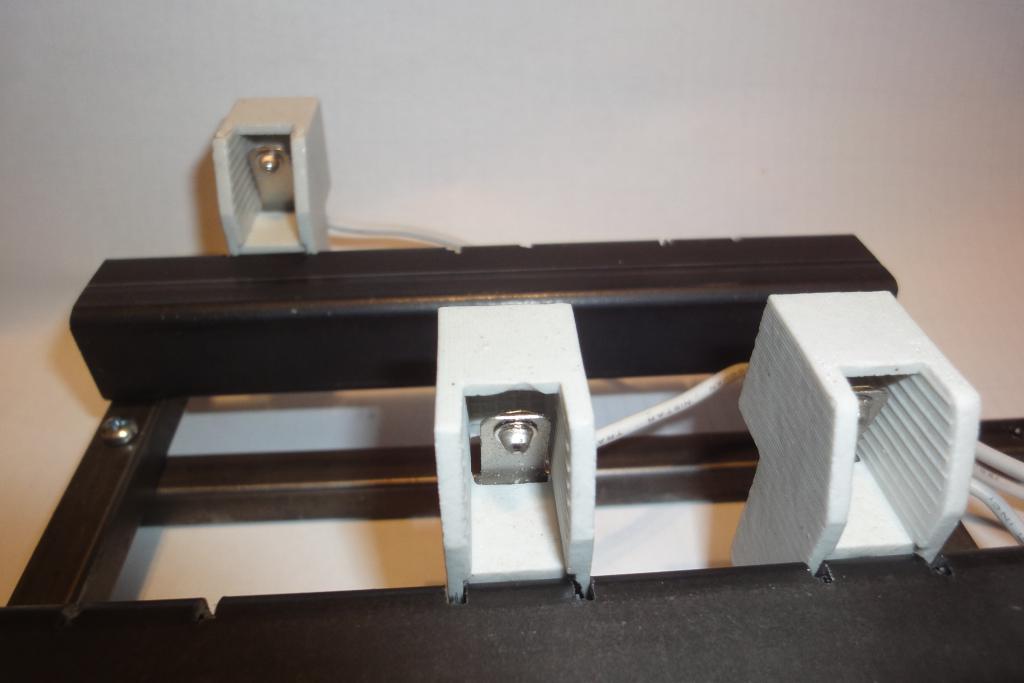
The R7s sockets needed to be mounted on some support construction. This was quite a problem, as specific spacing was needed in two different distances, and the sockets came as loose ones with a M4 screw built in but protruding only a short distance.
For attaching the sockets a steel 20x20mm square tube was chosen. To accommodate the protrusions on the ceramic body of the socket, cutouts were made on the tubes with a band saw, as pairs of tightly spaced parallel cuts.
Holes were drilled and M4 threads tapped for the holding screws.
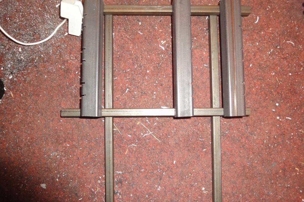
A frame for mounting the socket holders was made from 10x10mm square tubes. Holes with M3 threads were used to hold the assembly together, and for attachment to the connection box. The horizontal beams were made longer than strictly needed for the socket holders, in order to facilitate later attaching of a protective cage.
The holding tubes were attached to the frame using pairs of M3 screws.
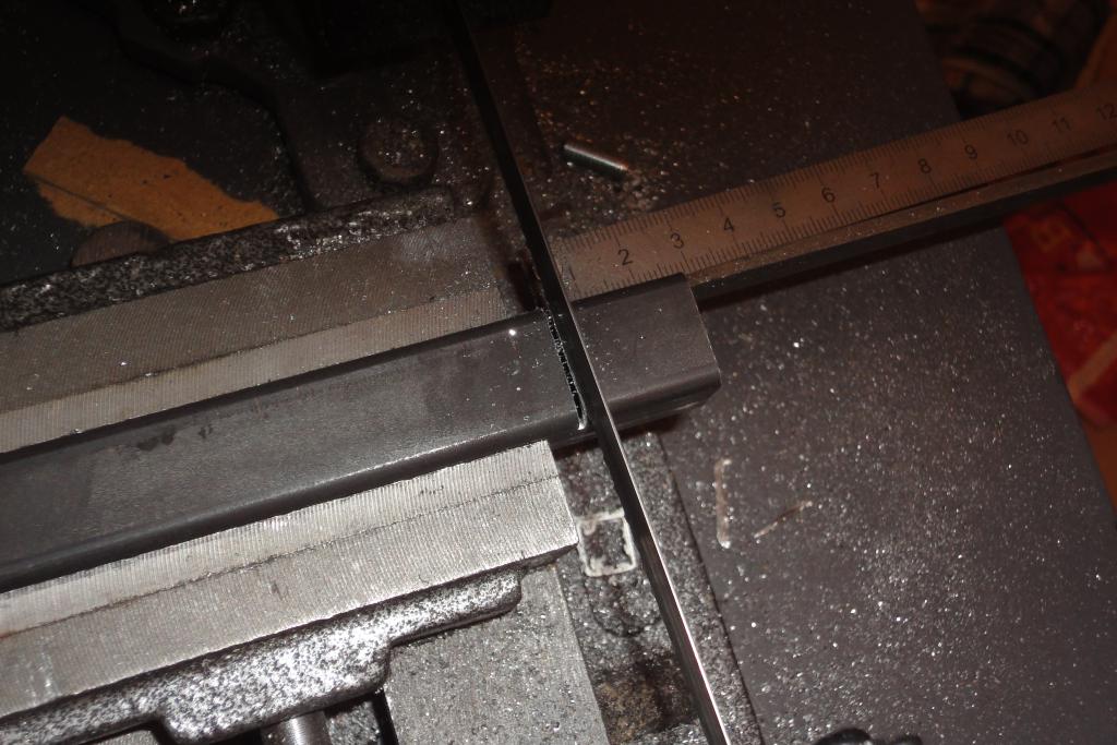 Lightbulb socket holder, slit being cut | 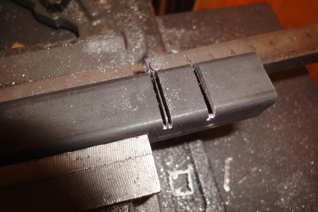 Lightbulb socket holder | 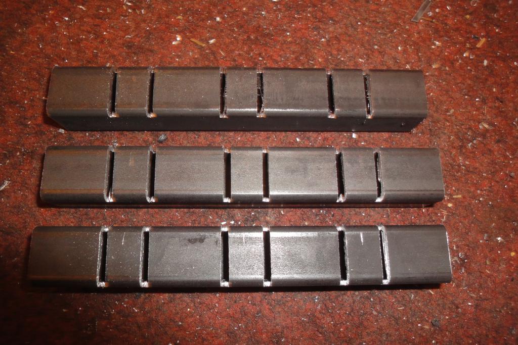 Lightbulb socket holder | 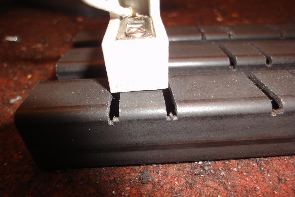 Lightbulb socket holder |
 Lightbulb socket holder | 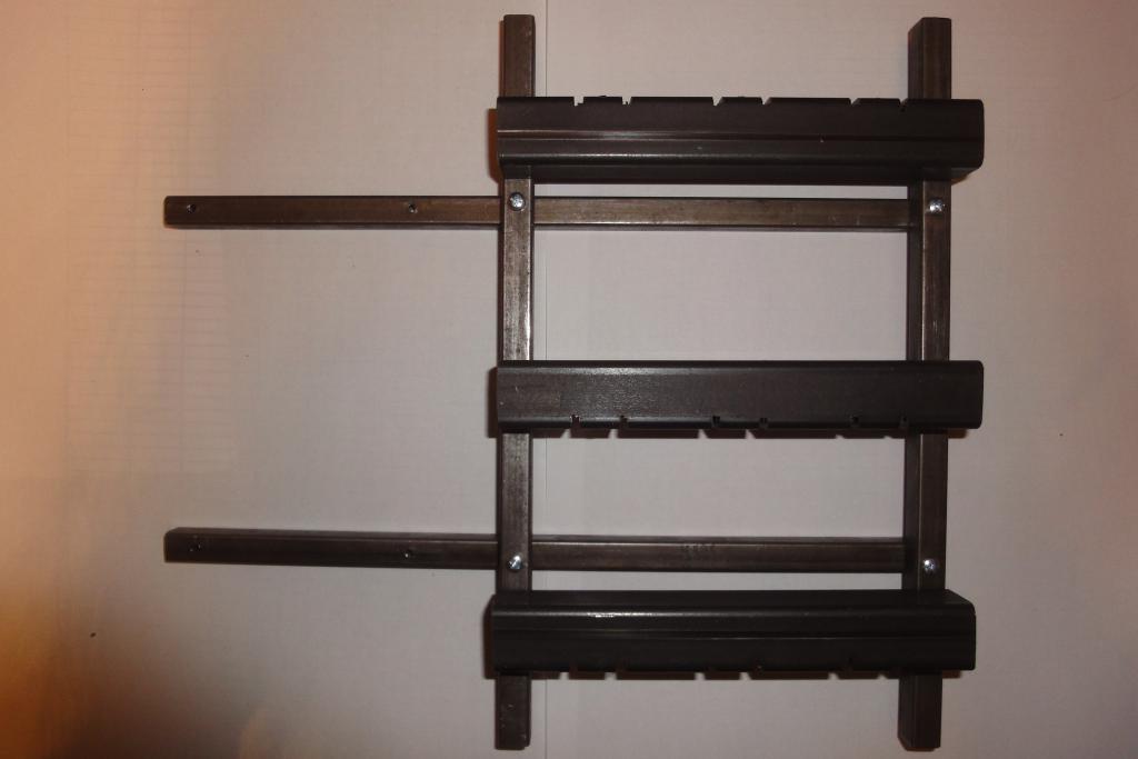 Lightbulb socket holder | 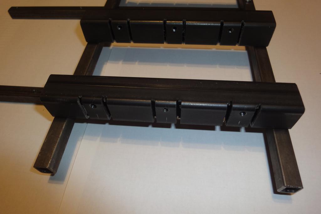 Lightbulb socket holder | 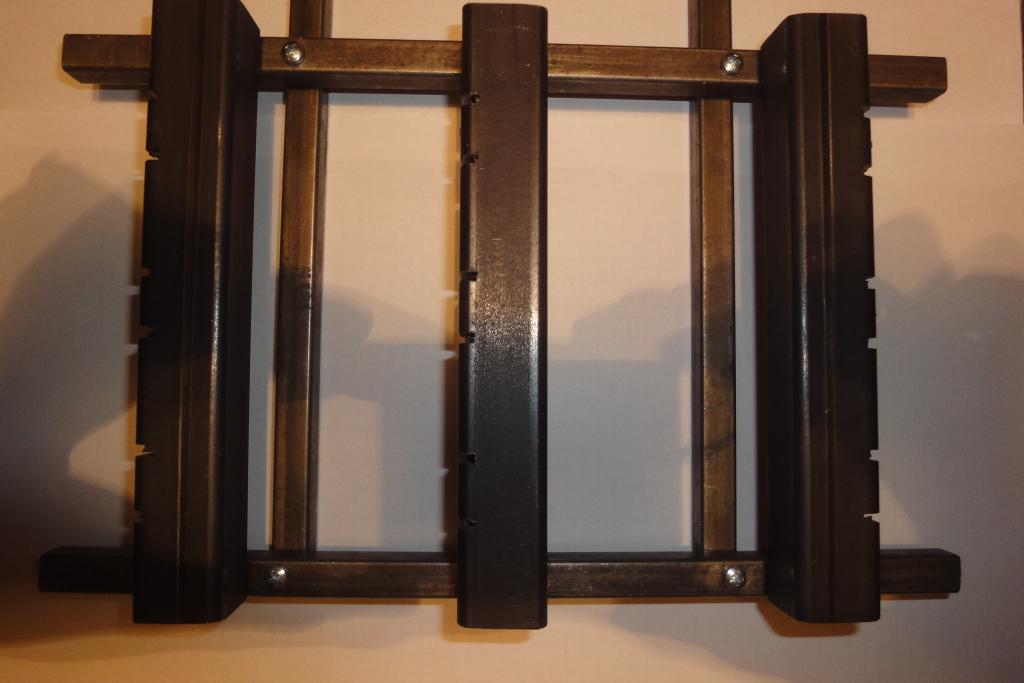 Lightbulb socket holder |
 Lightbulb socket holder | 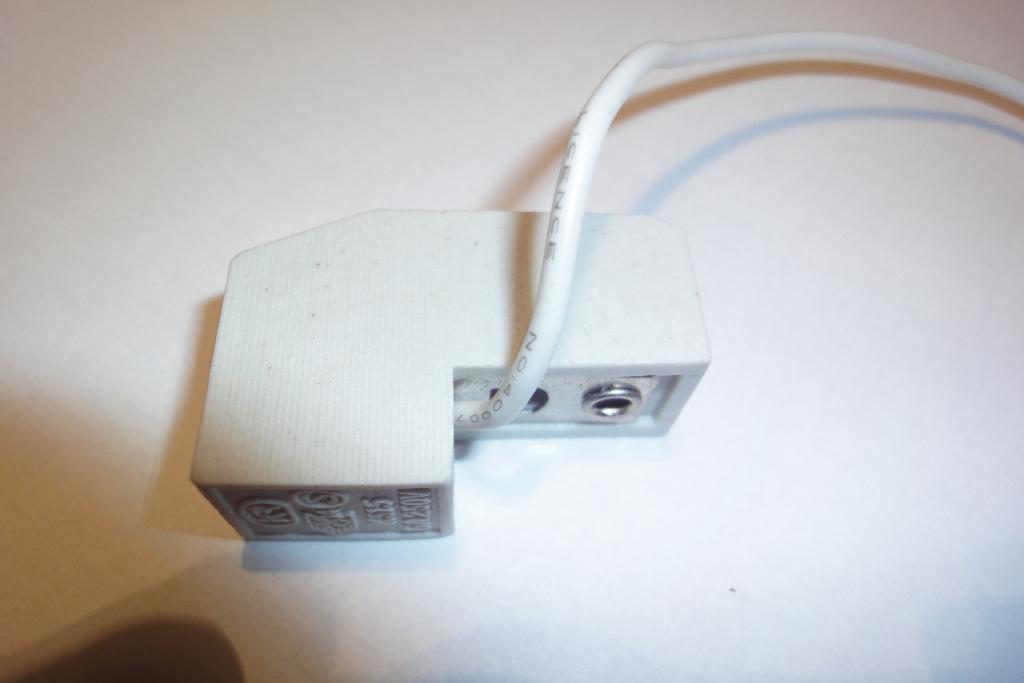 R7s socket | 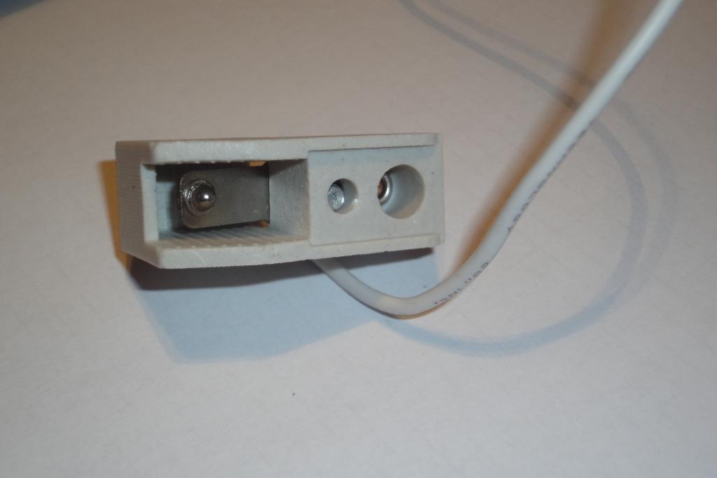 R7s socket | 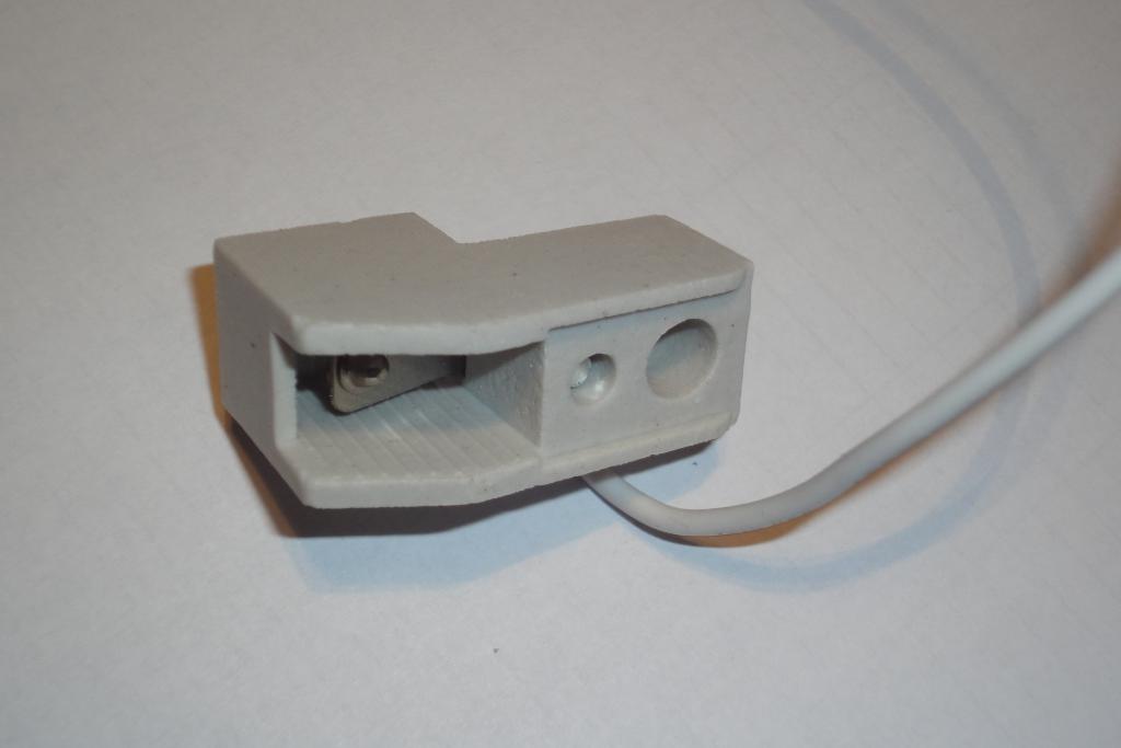 R7s socket |
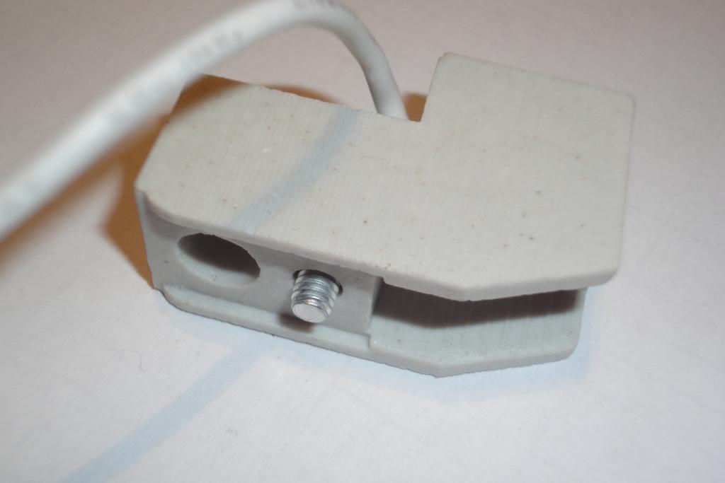 R7s socket | 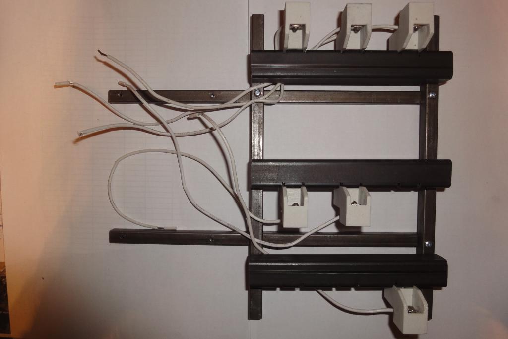 Sockets on holder | 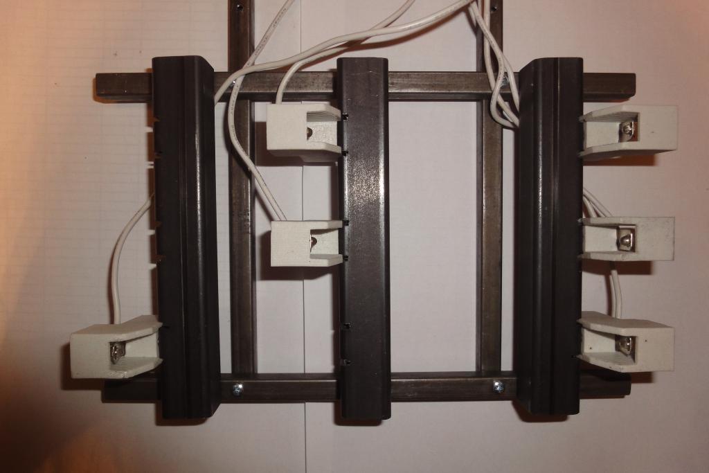 Sockets on holder | 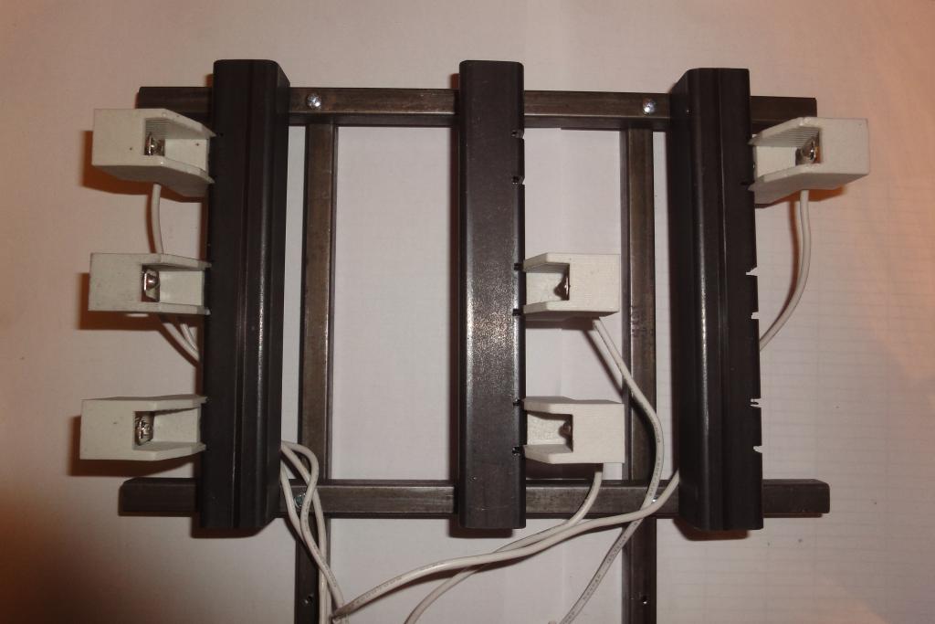 Sockets on holder |
 Sockets on holder | 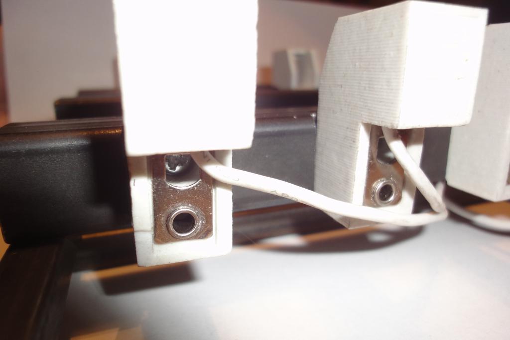 Sockets on holder | 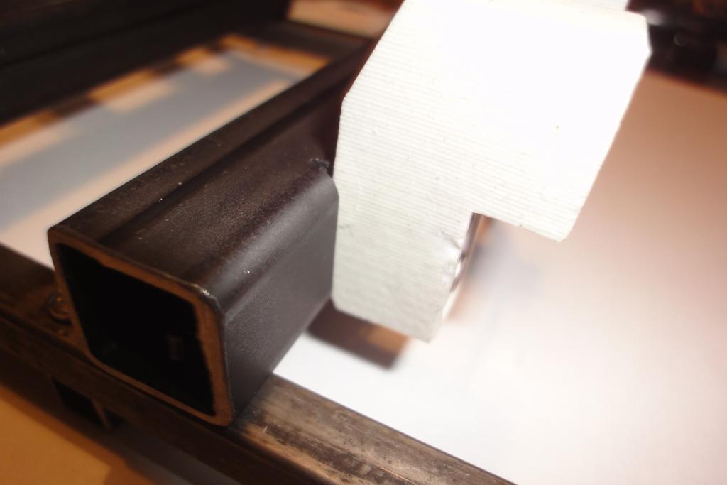 Sockets on holder | 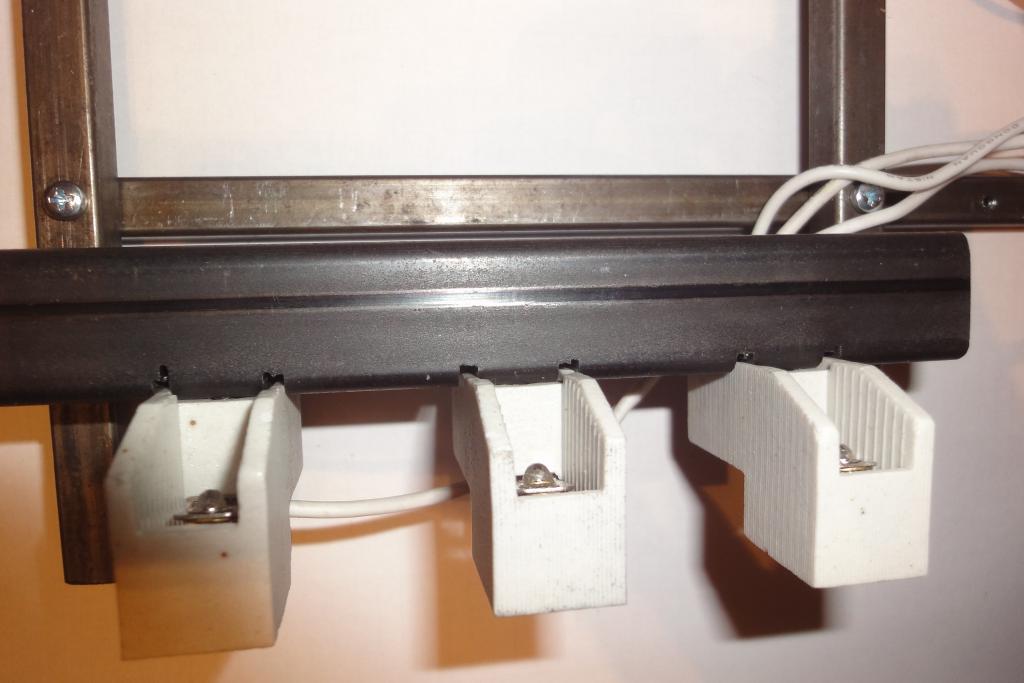 Sockets on holder |
 Sockets on holder | 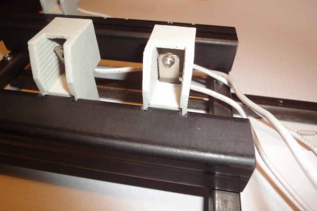 Sockets on holder | 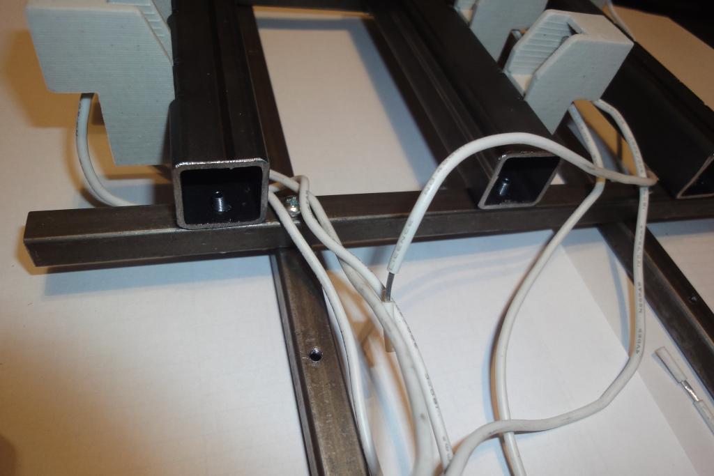 Sockets on holder | 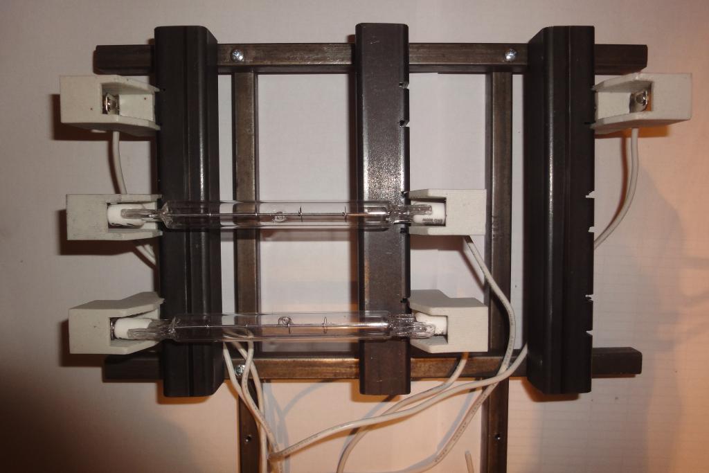 Sockets with bulbs |
 Sockets with bulbs |
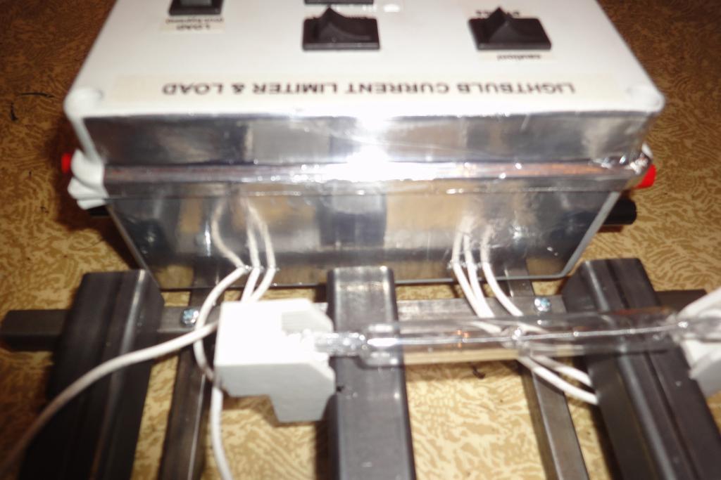
The wiring was done by wires soldered to the switch contacts. A better way would be using crimped blade connectors ("fastons"). The lightbulb sockets were connected using a length of electrical terminal strip.
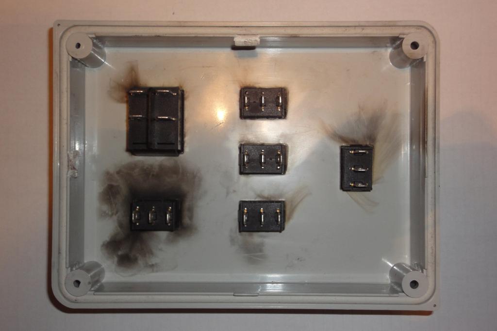 Assembling the lid | 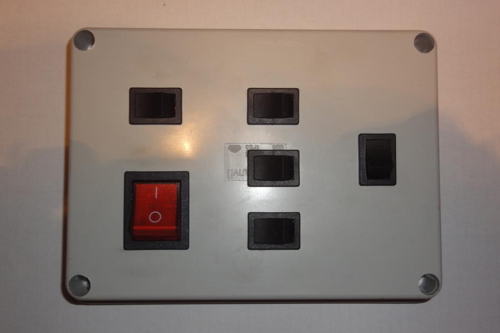 Assembling the lid | 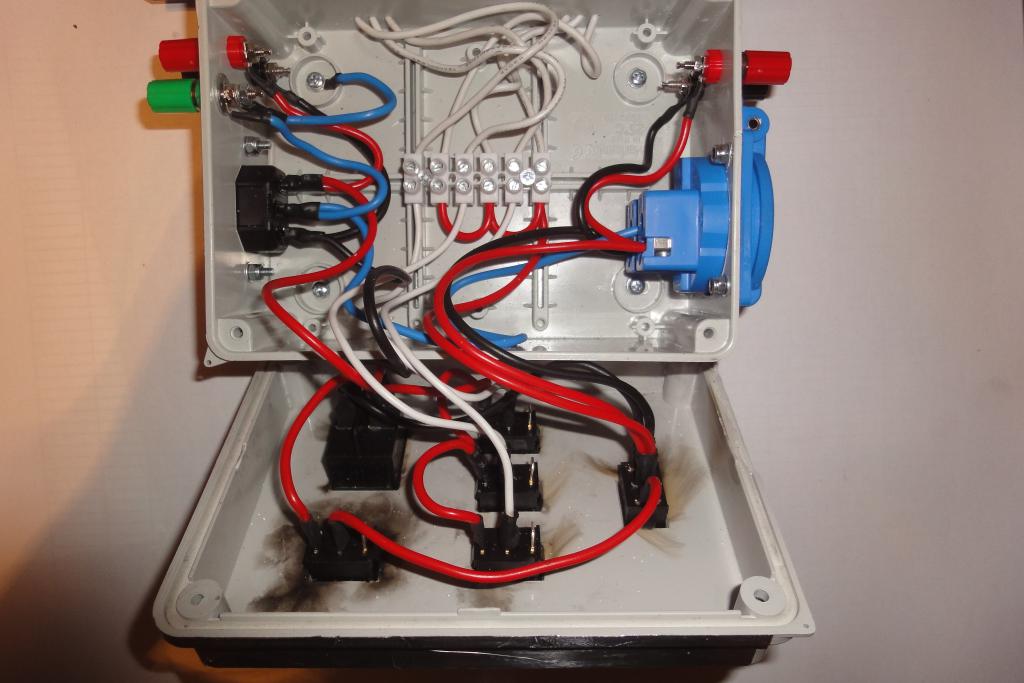 Wiring | 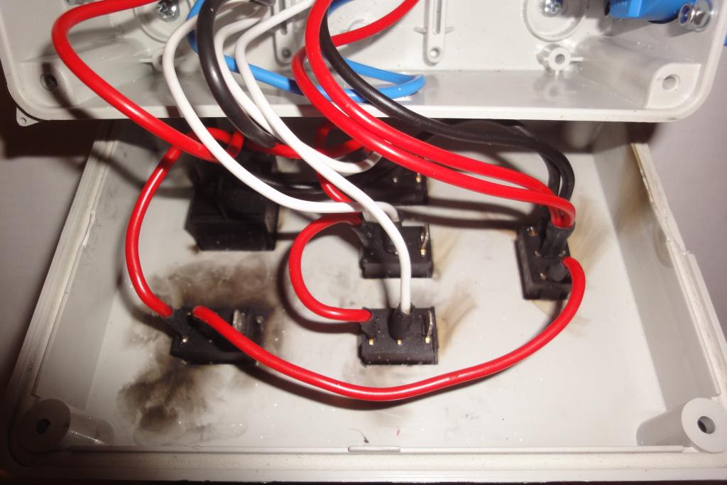 Wiring |
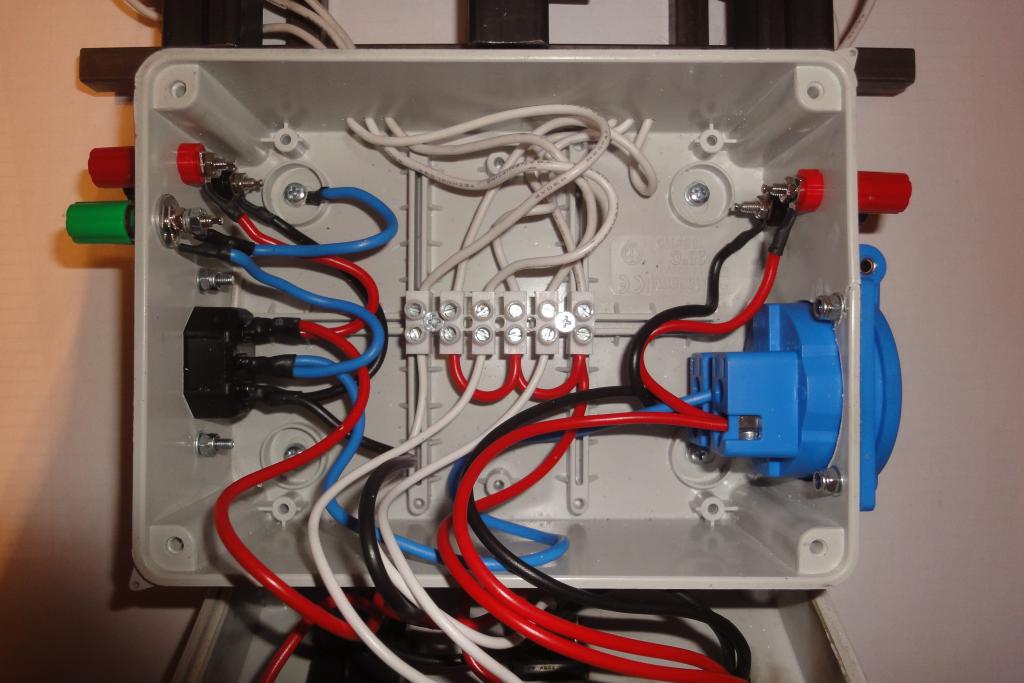 Wiring | 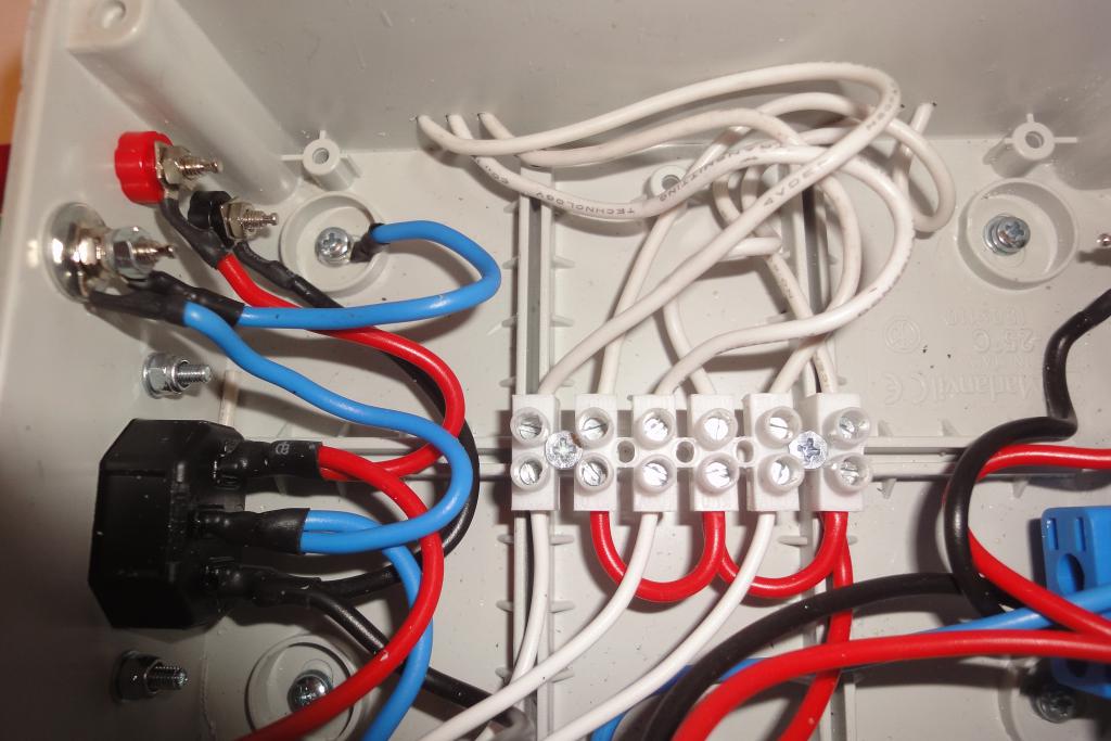 Wiring | 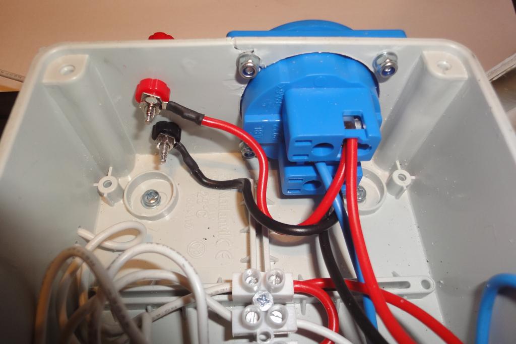 Wiring | 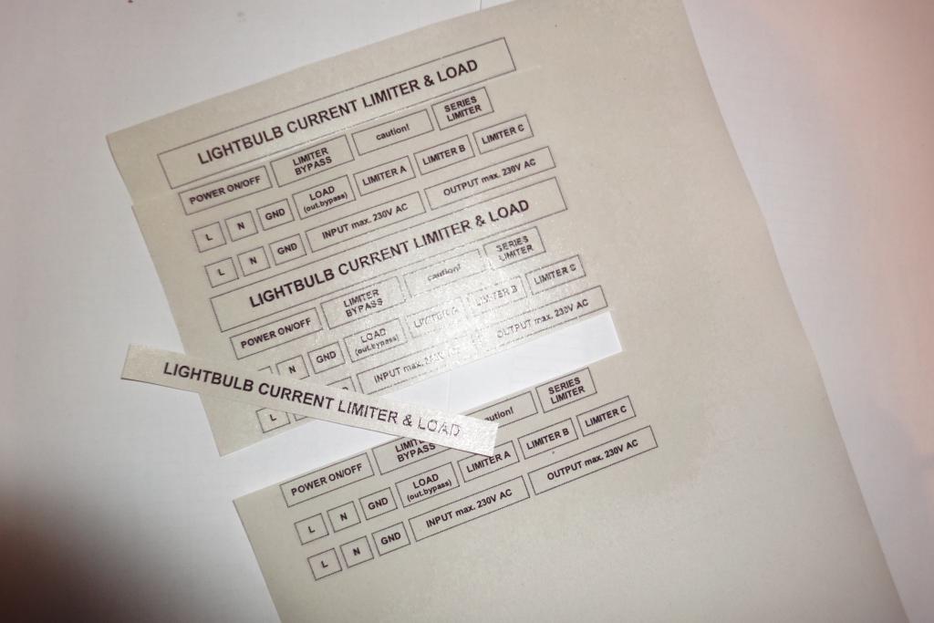 Case labels printout |
After first field test, the binding posts were moved to the front panel, and the ammeter attachment pair and a bypass switch were added.
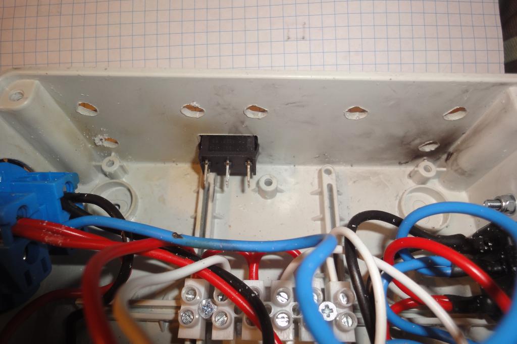 Ammeter bypass switch | 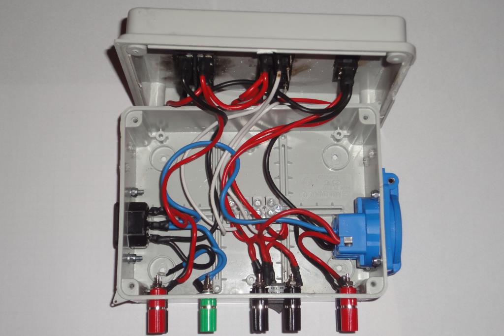 Modded wiring | 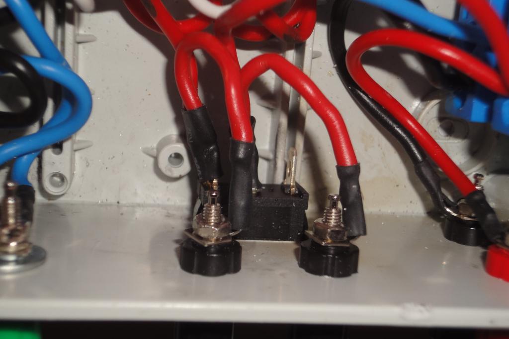 Modded wiring | 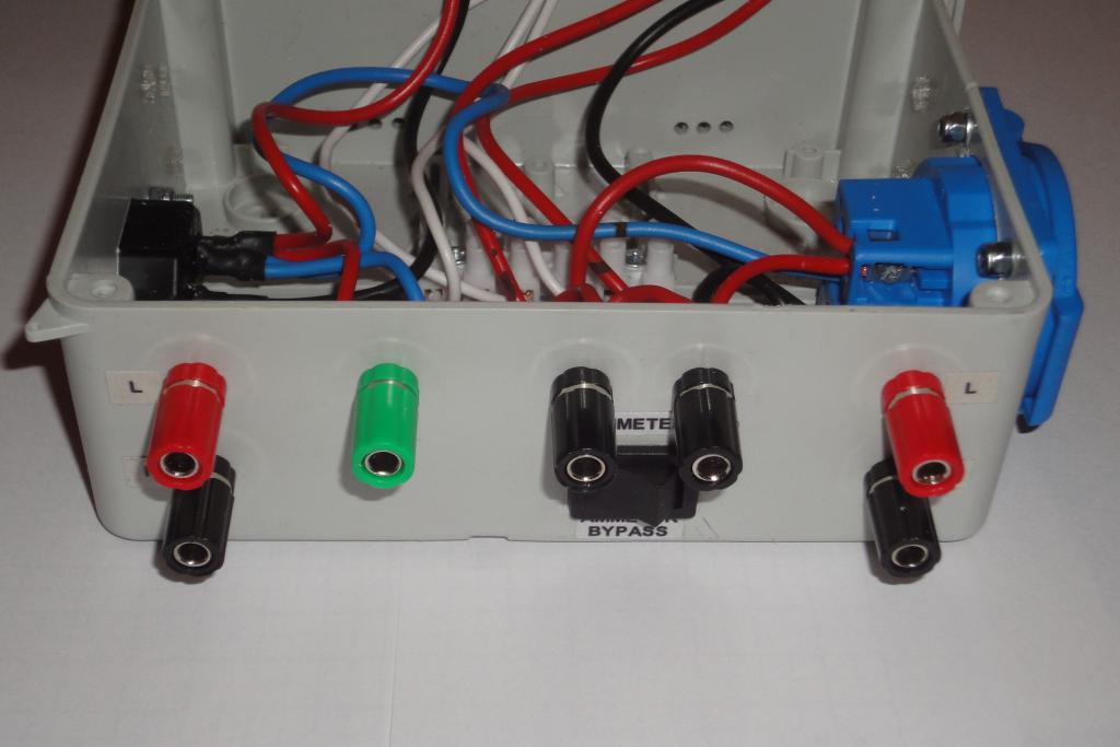 Front panel |
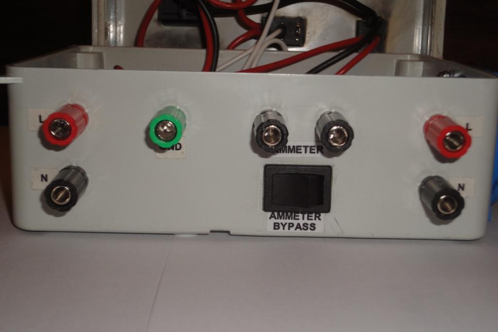 Front panel |
A problem was discovered during documenting. The ammeter was connected after the lamps, so it was shorted and nonfunctional in the load mode. It was moved between the main power switch and the lamp switches.
 Ammeter correction wiring | 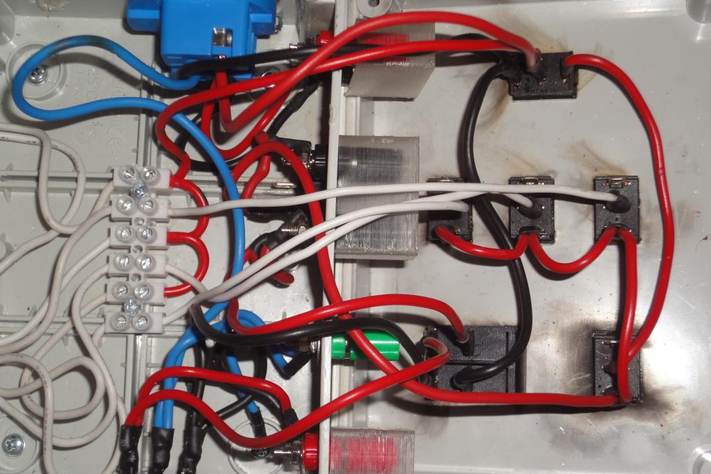 Ammeter correction wiring | 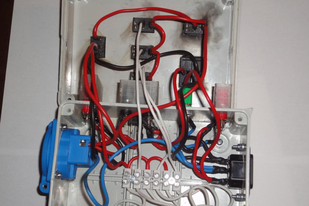 Ammeter correction wiring | 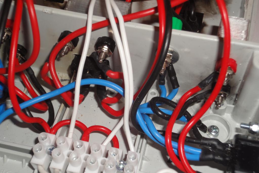 Ammeter correction wiring |
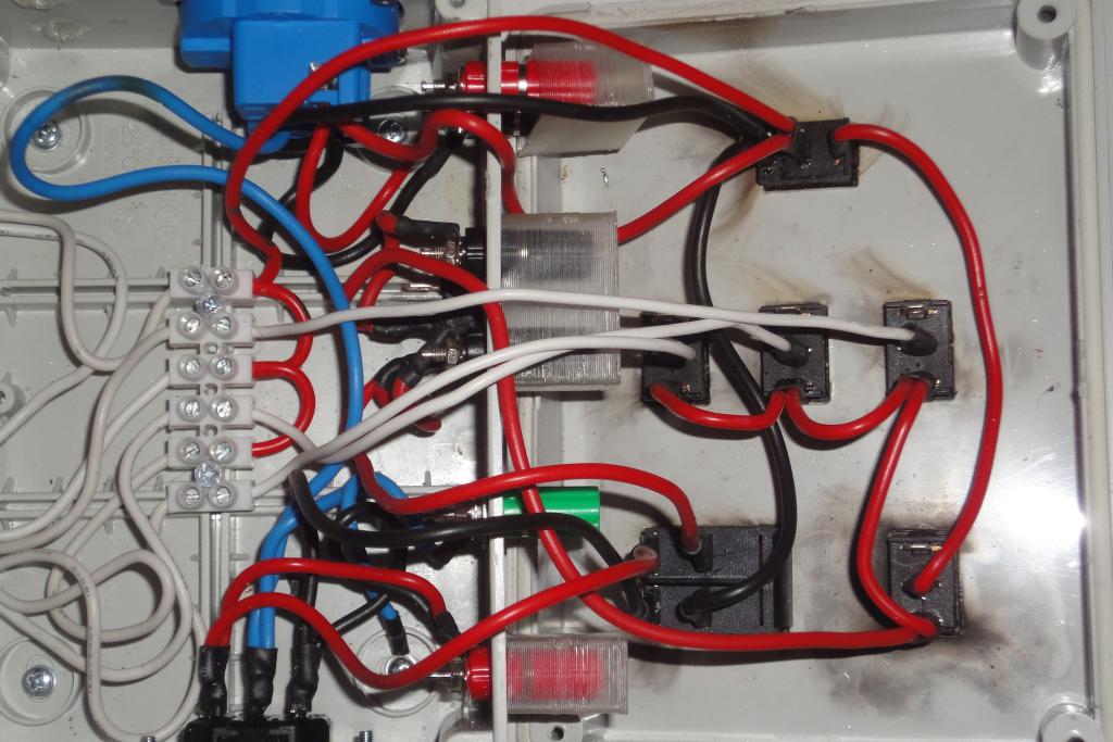 Ammeter correction wiring |
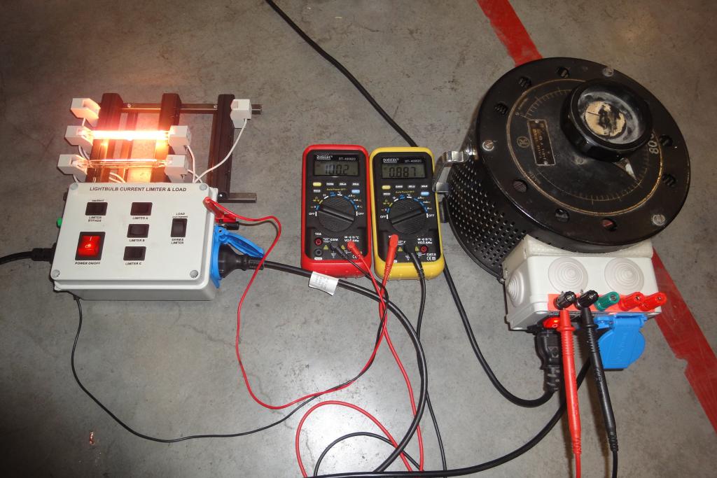
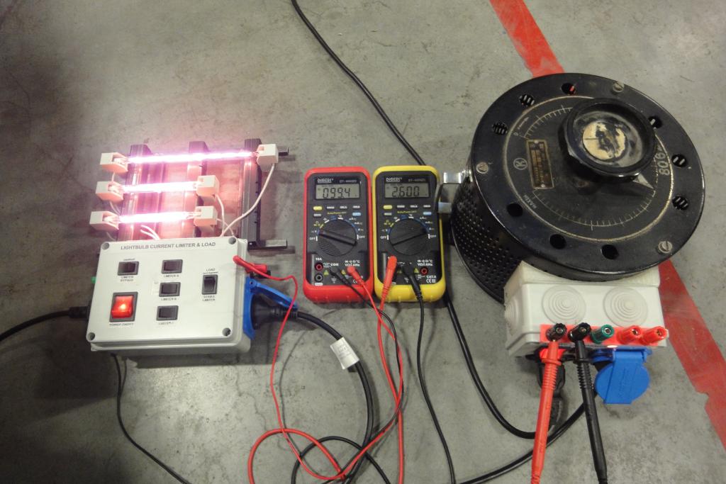
The unit was tested in the mode of artificial load, first on a variac, then directly on mains. The lamps when run on full voltage are BRIGHT and HOT.
Adhesive aluminium foil was attached to the lamps-facing side of the connection box to provide at least some protection against radiated heat.
Covers for binding posts were designed and 3d-printed to avoid accidental touch of live
metal connectors.
 First assembly | 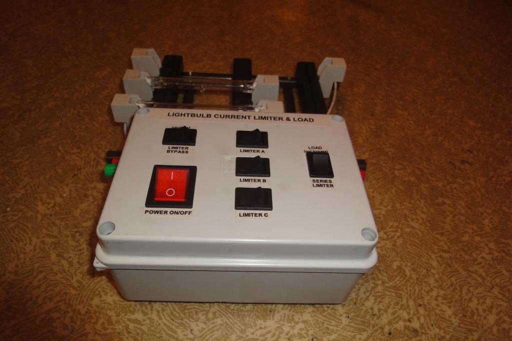 First assembly | 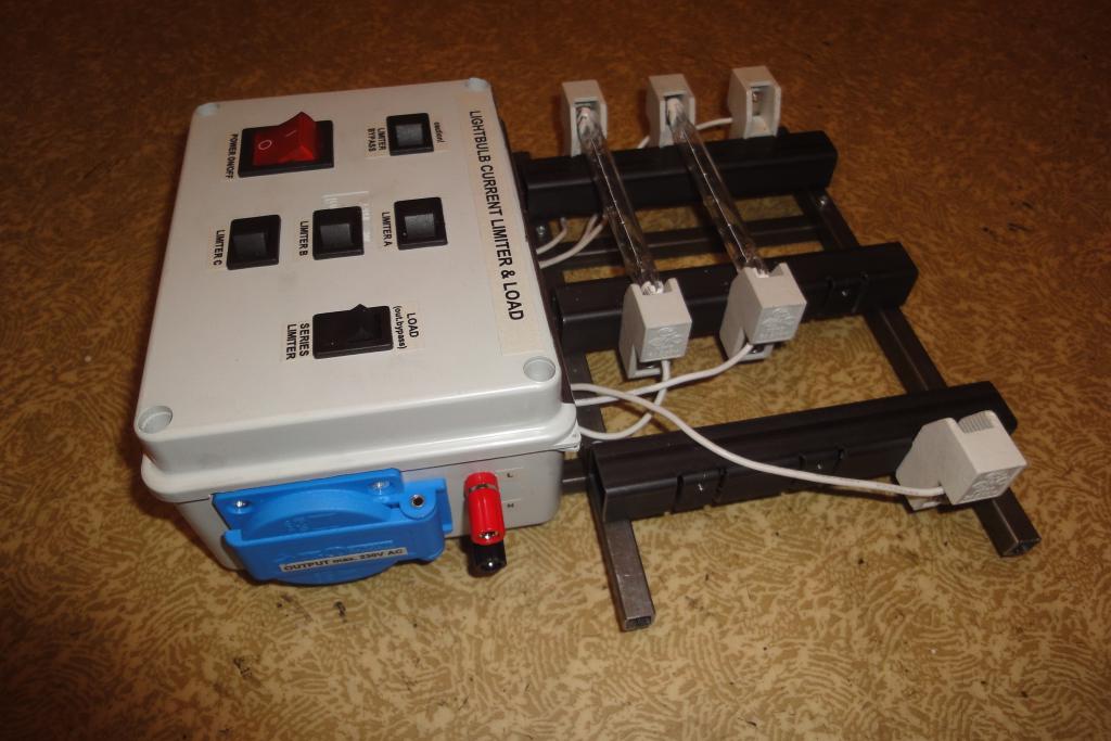 First assembly | 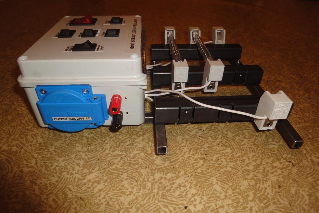 First assembly |
 First assembly | 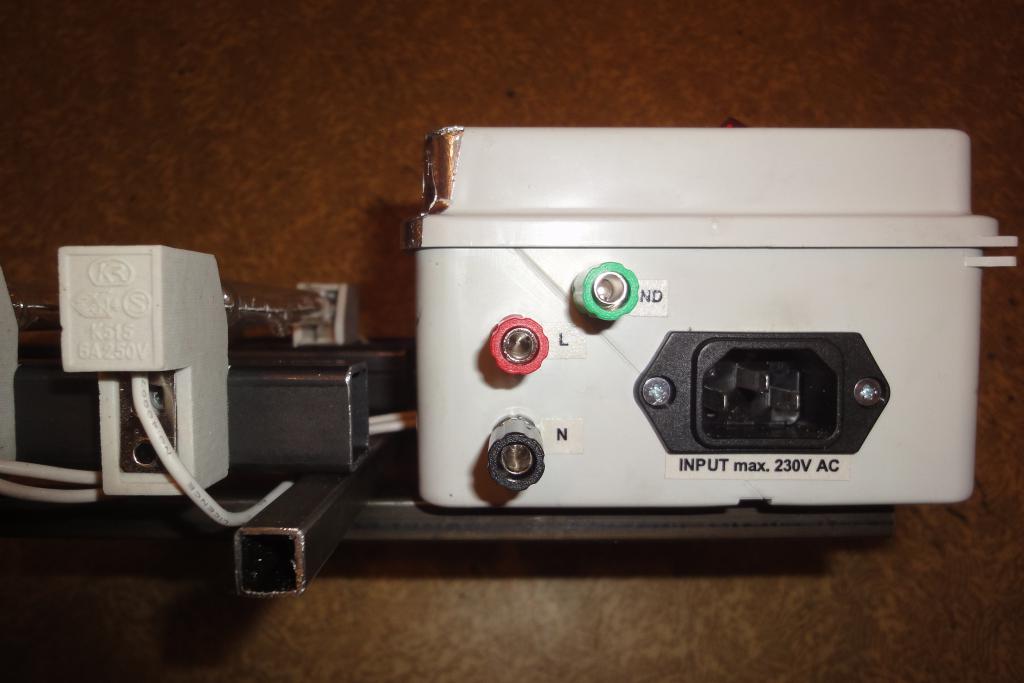 First assembly | 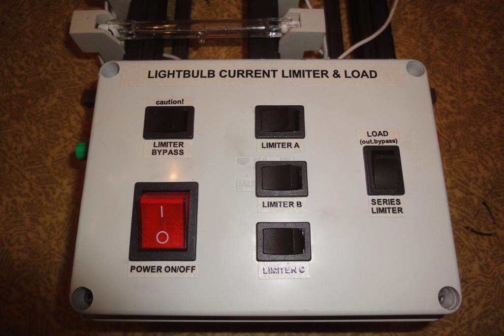 First assembly | 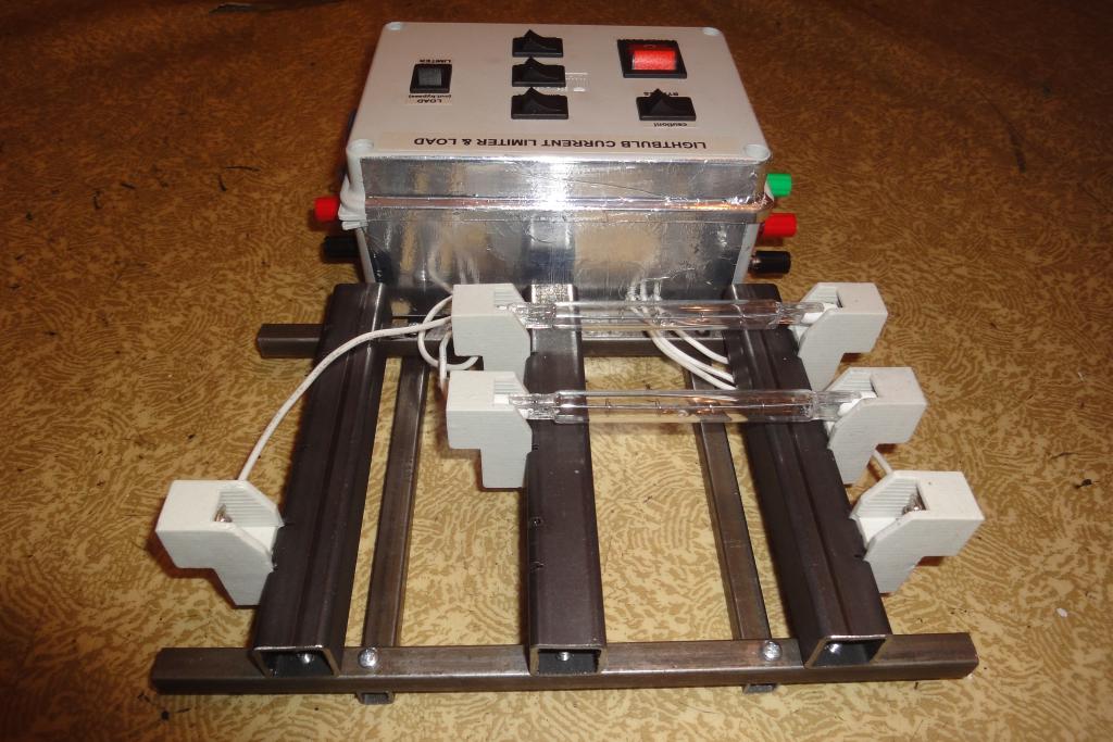 First assembly |
 Aluminium foil for heat reflection |
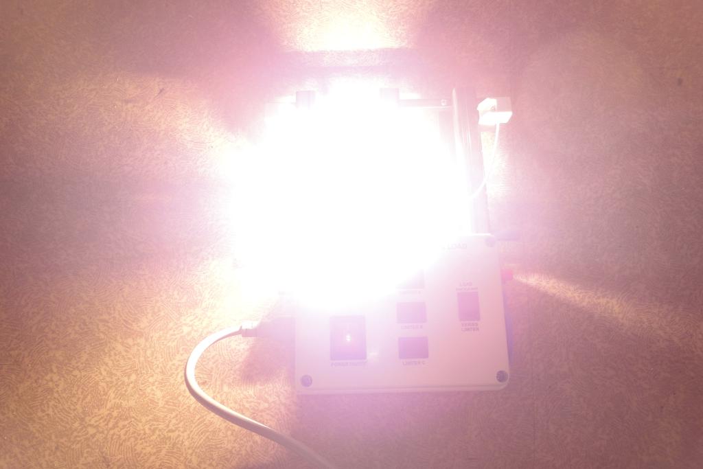 Lit-up assembly | 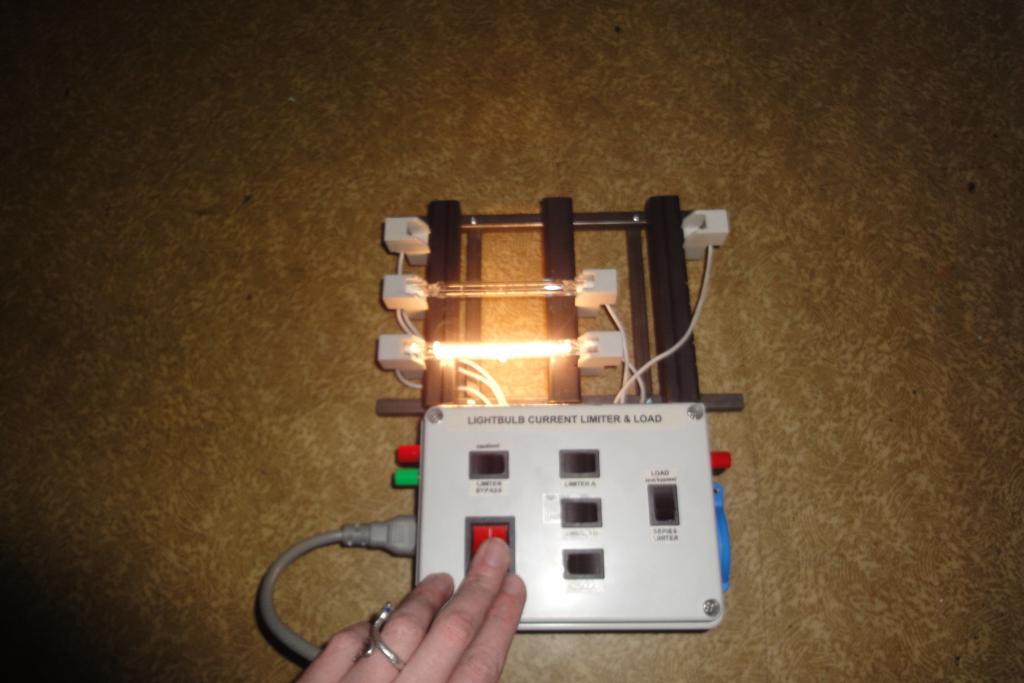 Lit-up assembly | 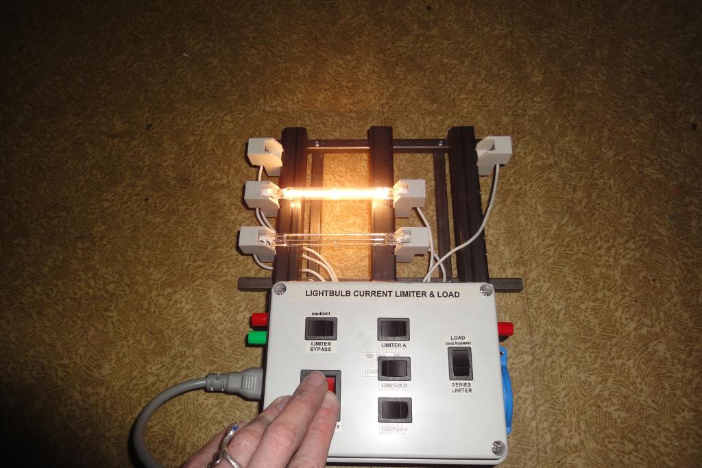 Lit-up assembly | 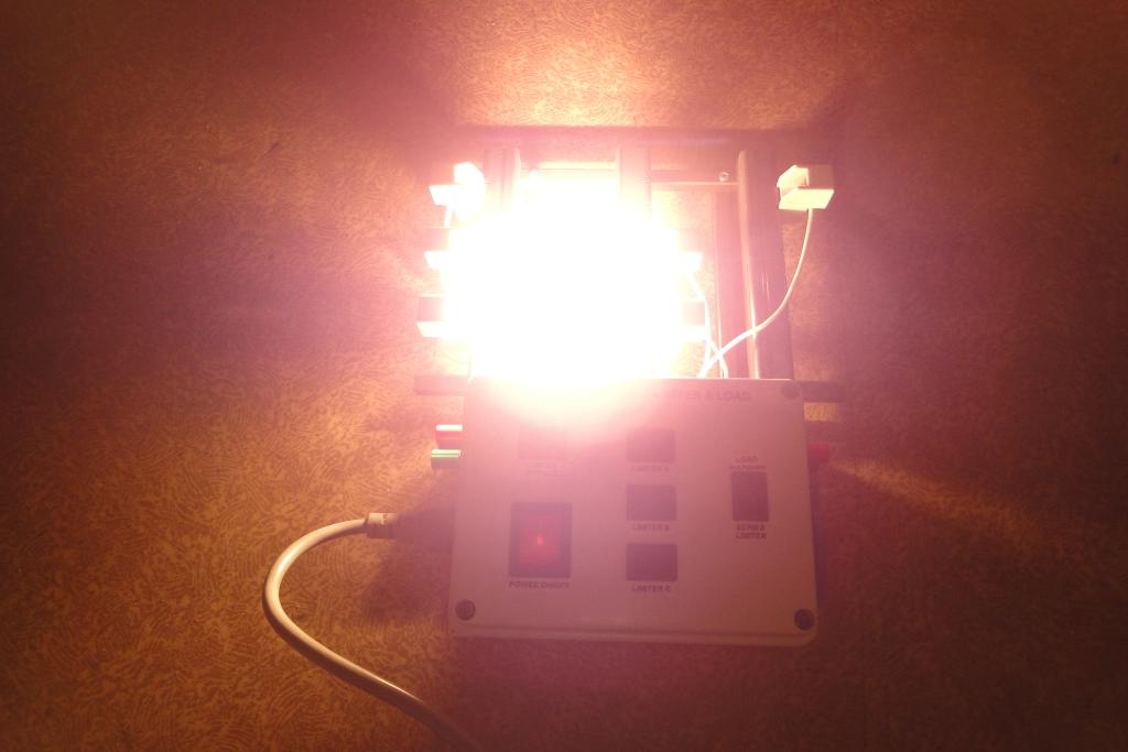 Lit-up assembly |
 Lit-up assembly |
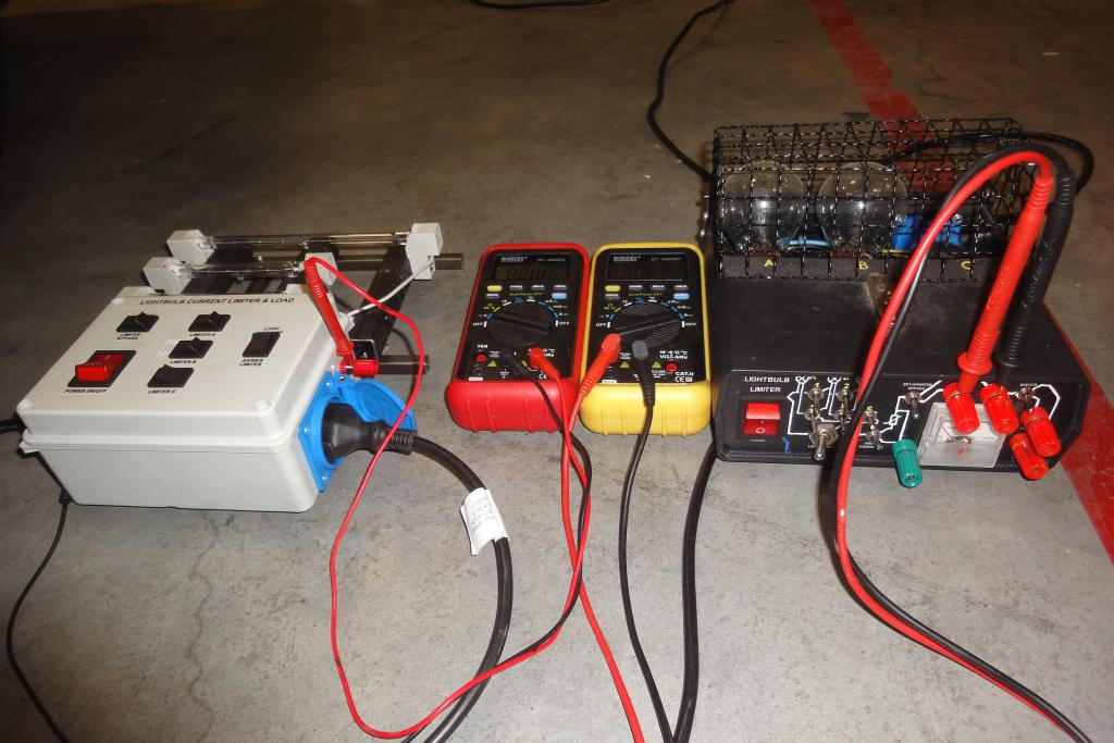
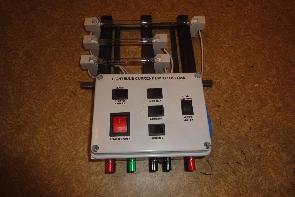 Finished assembly | 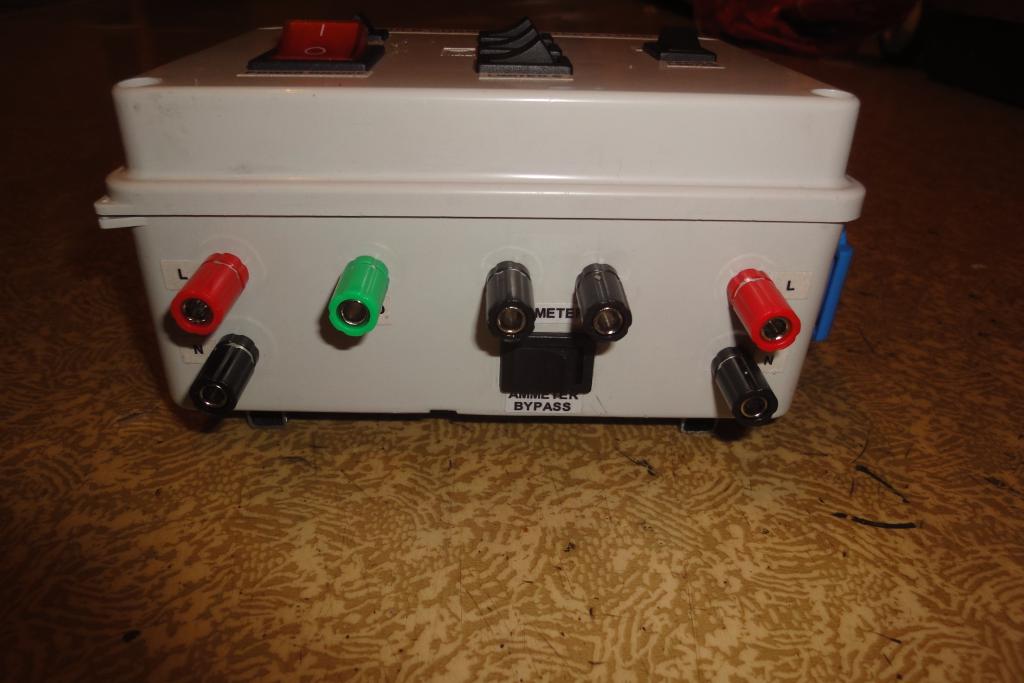 Finished assembly | 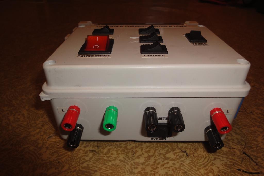 Finished assembly | 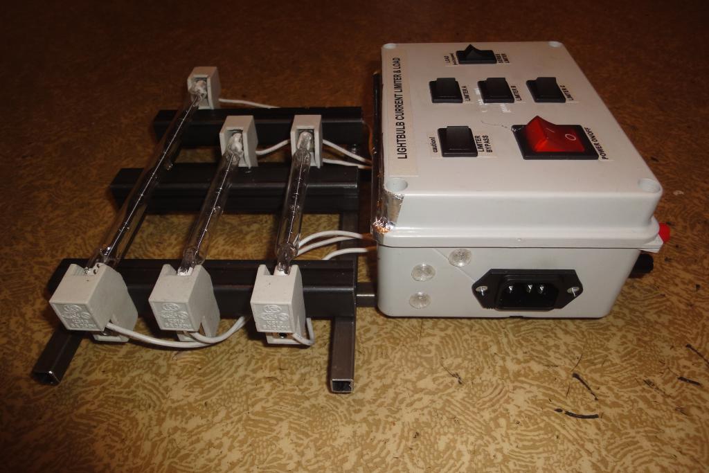 Finished assembly |
 Finished assembly | 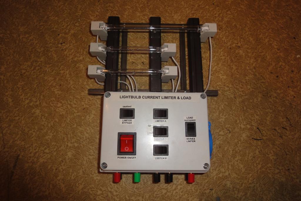 Finished assembly | 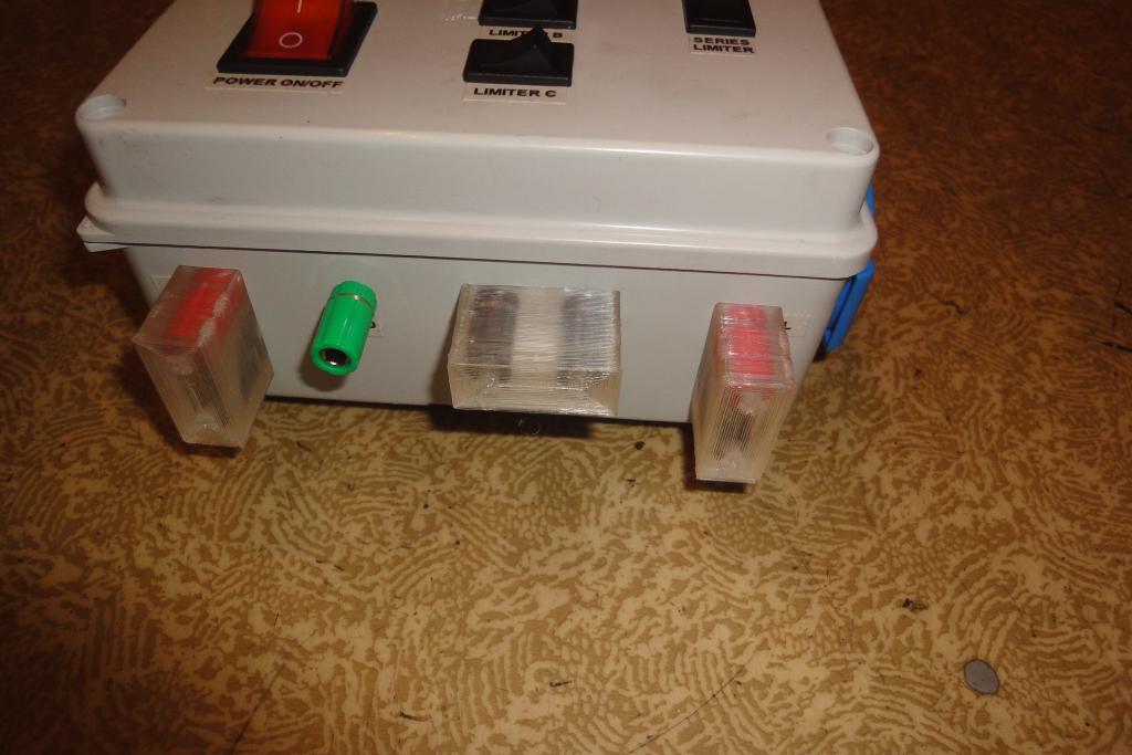 Finished assembly | 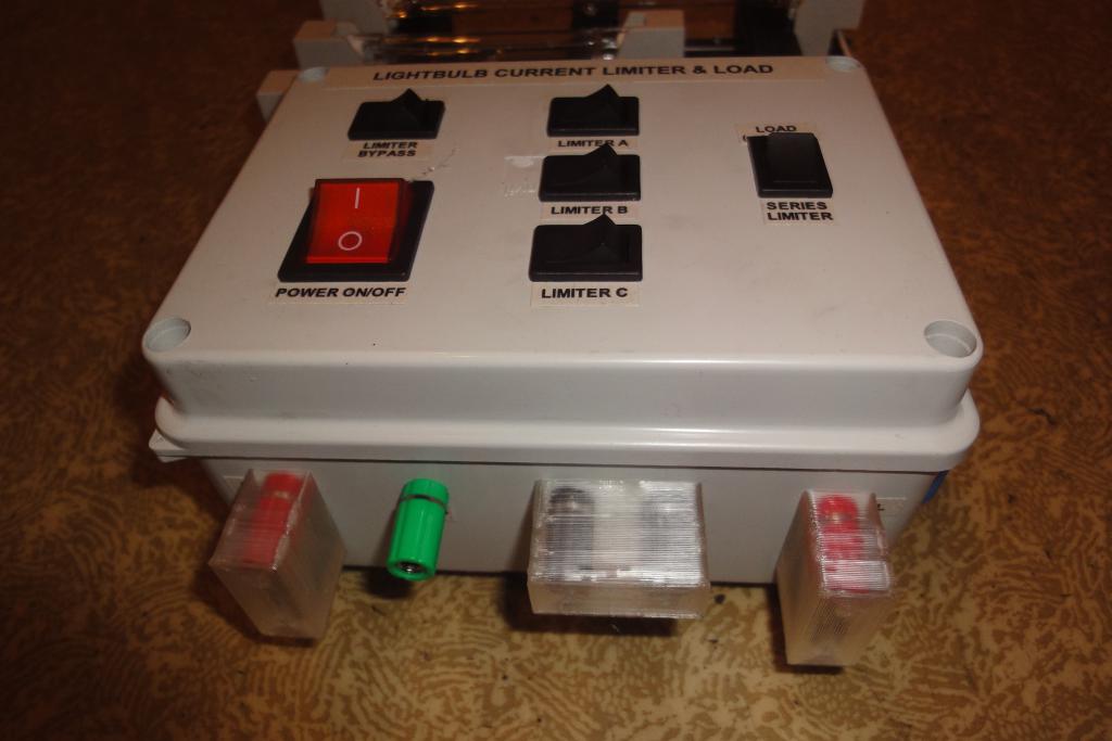 Finished assembly |
The device was tested on a prototype electric car, as both a load (for discharging a 100V battery and for sinking power from an engine controller) and a series current limiter (for charging test, using motor controller as a rectifier).
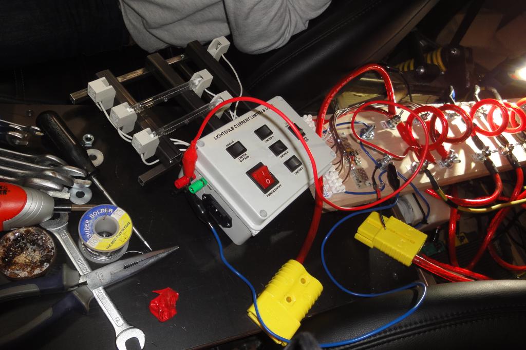 Field deployment, battery load | 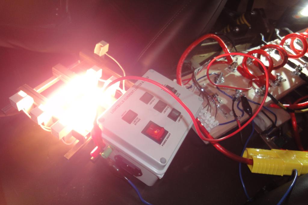 Field deployment, battery load | 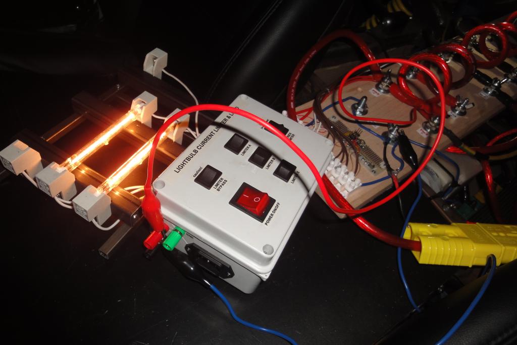 Field deployment, battery load | 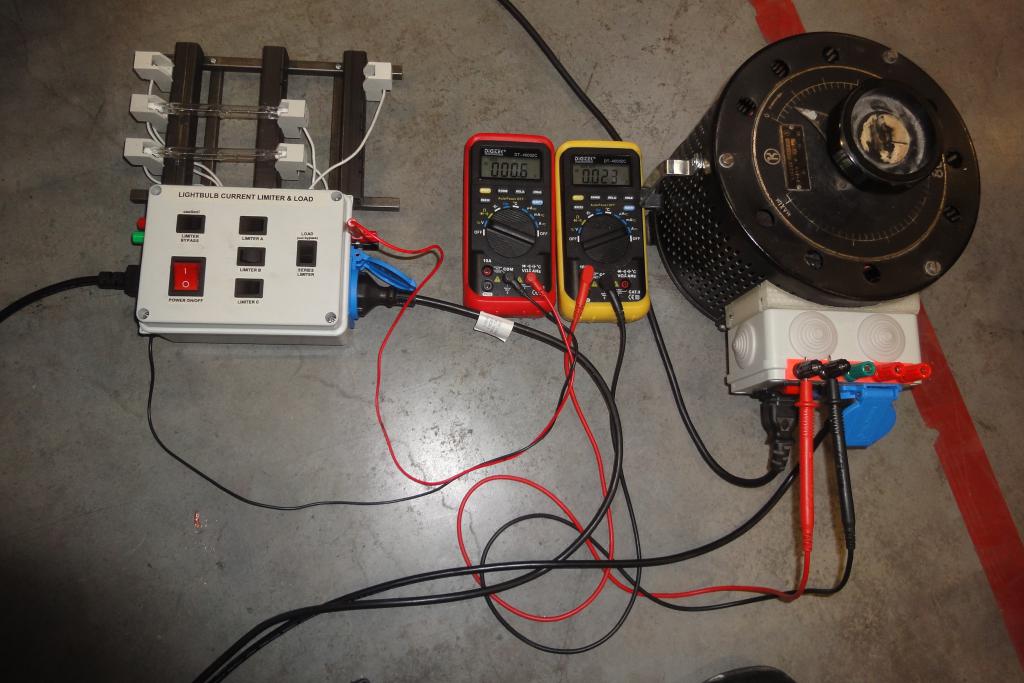 Field deployment, variac charging |
 Field deployment, variac charging | 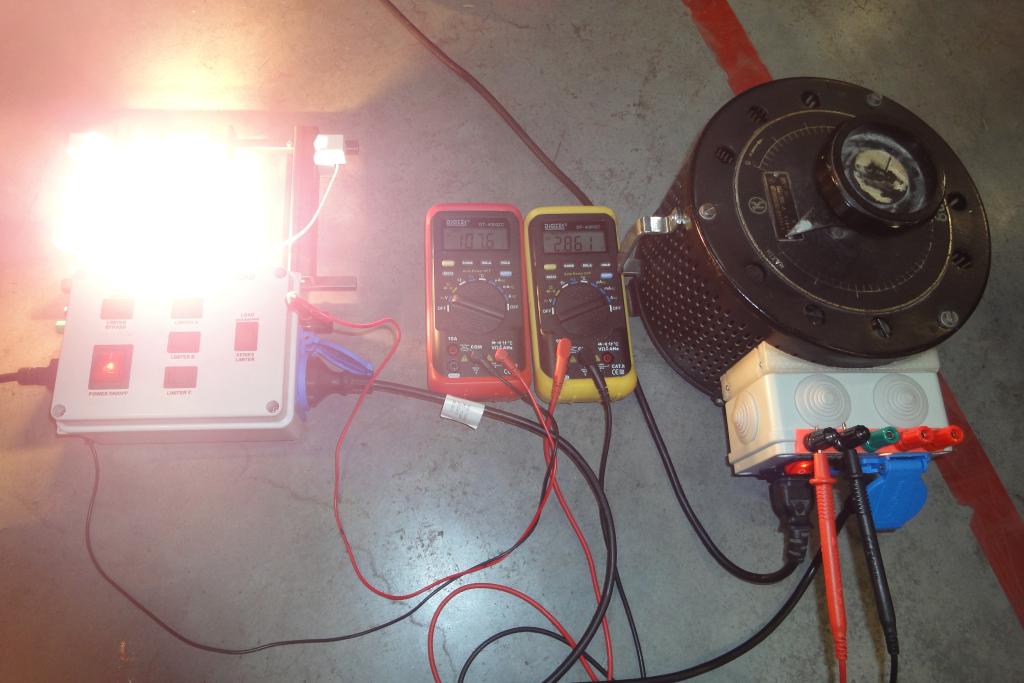 Field deployment, variac charging | 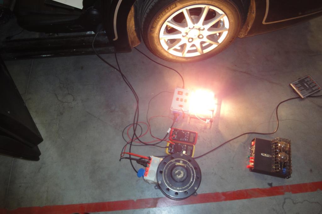 Field deployment, variac charging |  Field deployment, variac charging |
 Field deployment, variac charging | 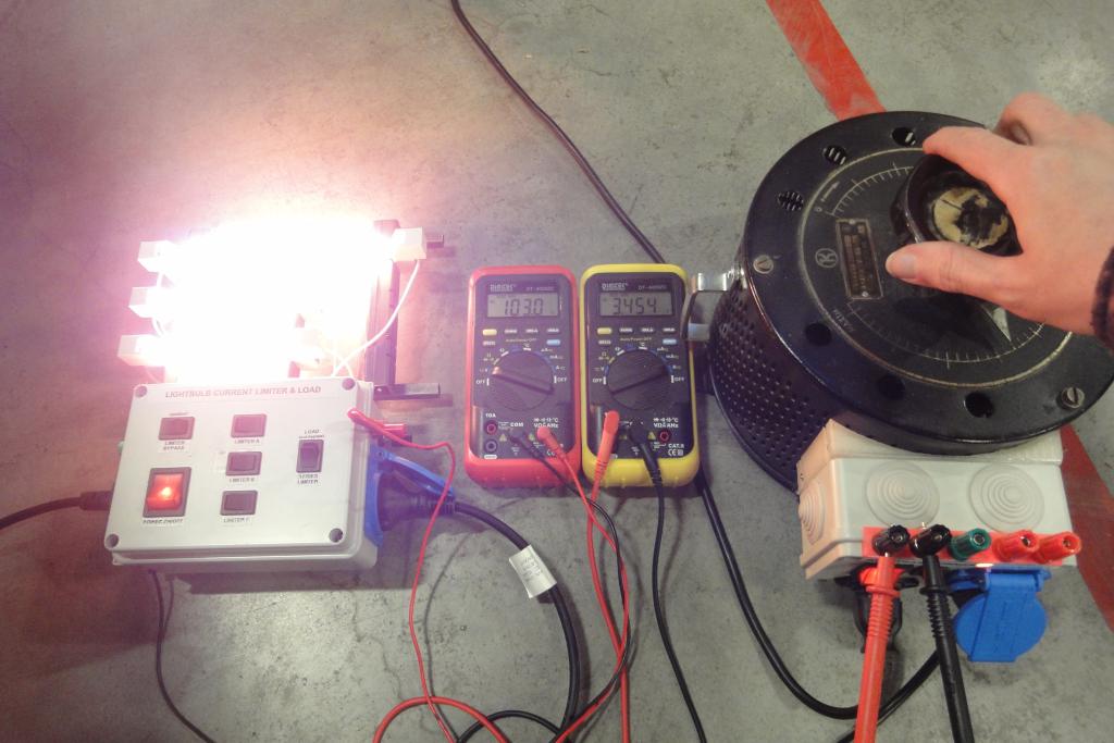 Field deployment, variac charging | 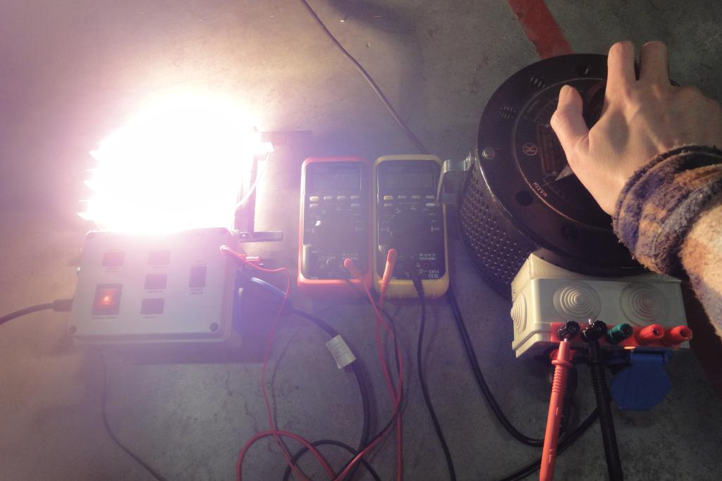 Field deployment, variac charging | 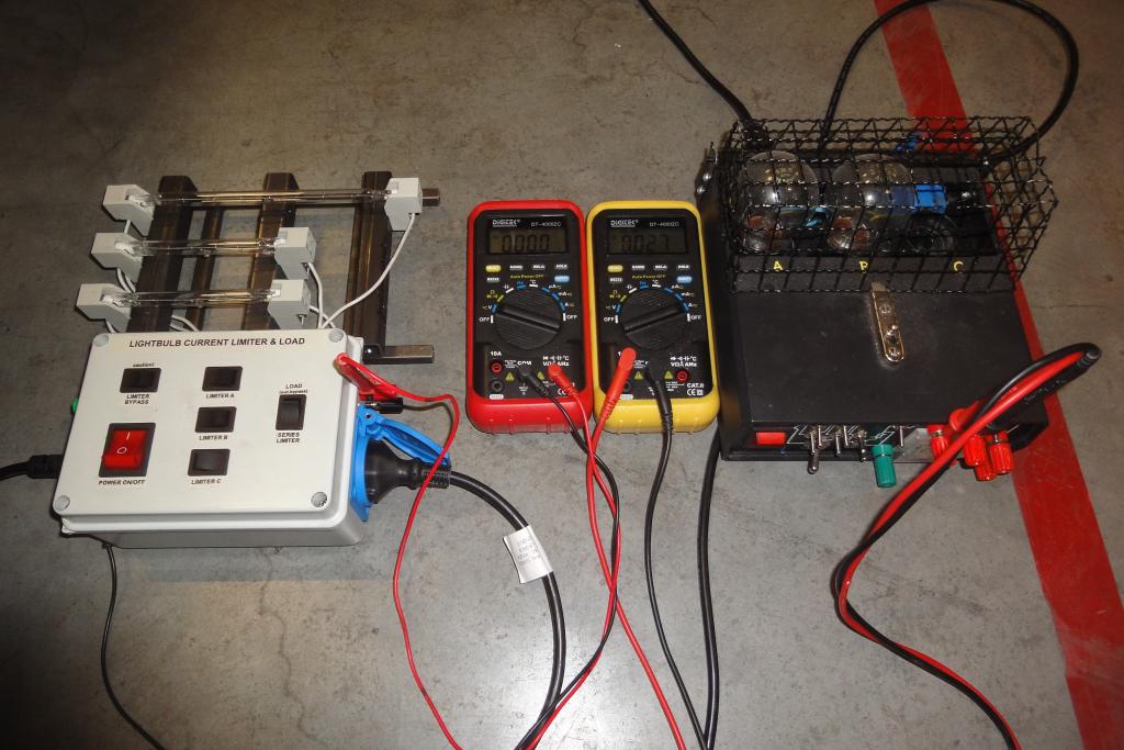 Field deployment, direct charging |
 Field deployment, direct charging | 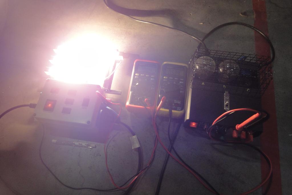 Field deployment, direct charging | 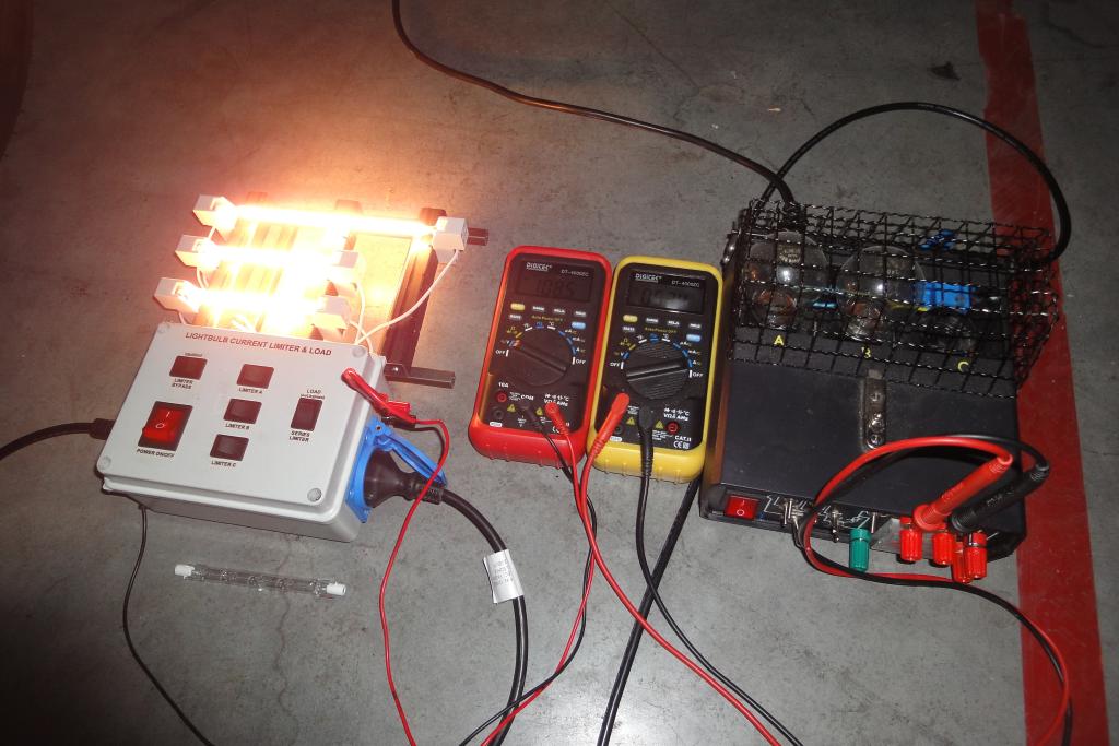 Field deployment, direct charging |
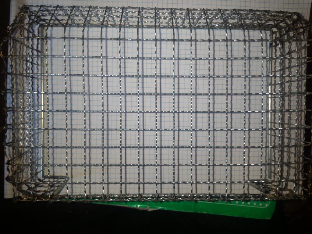
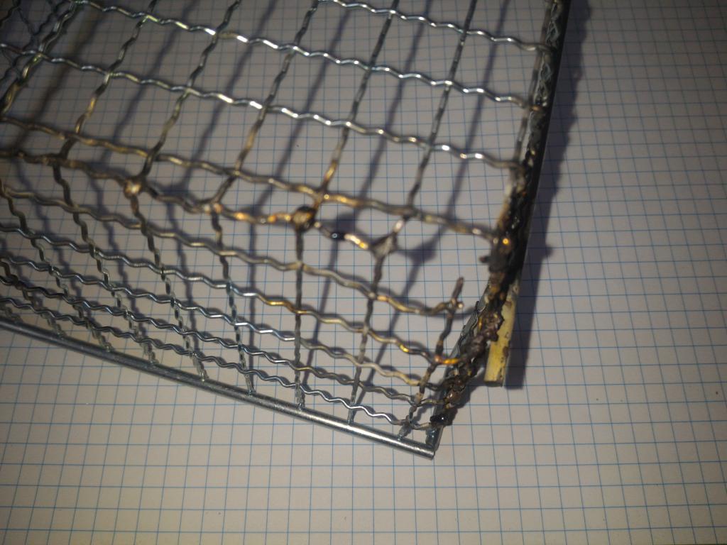
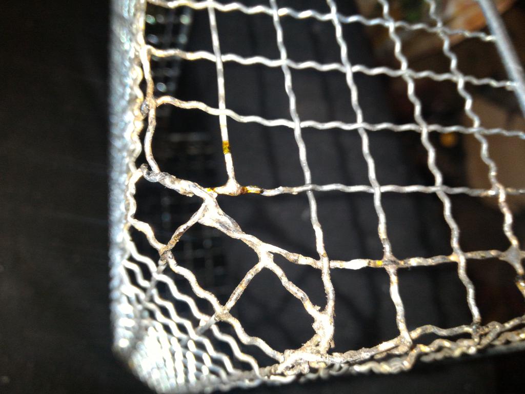
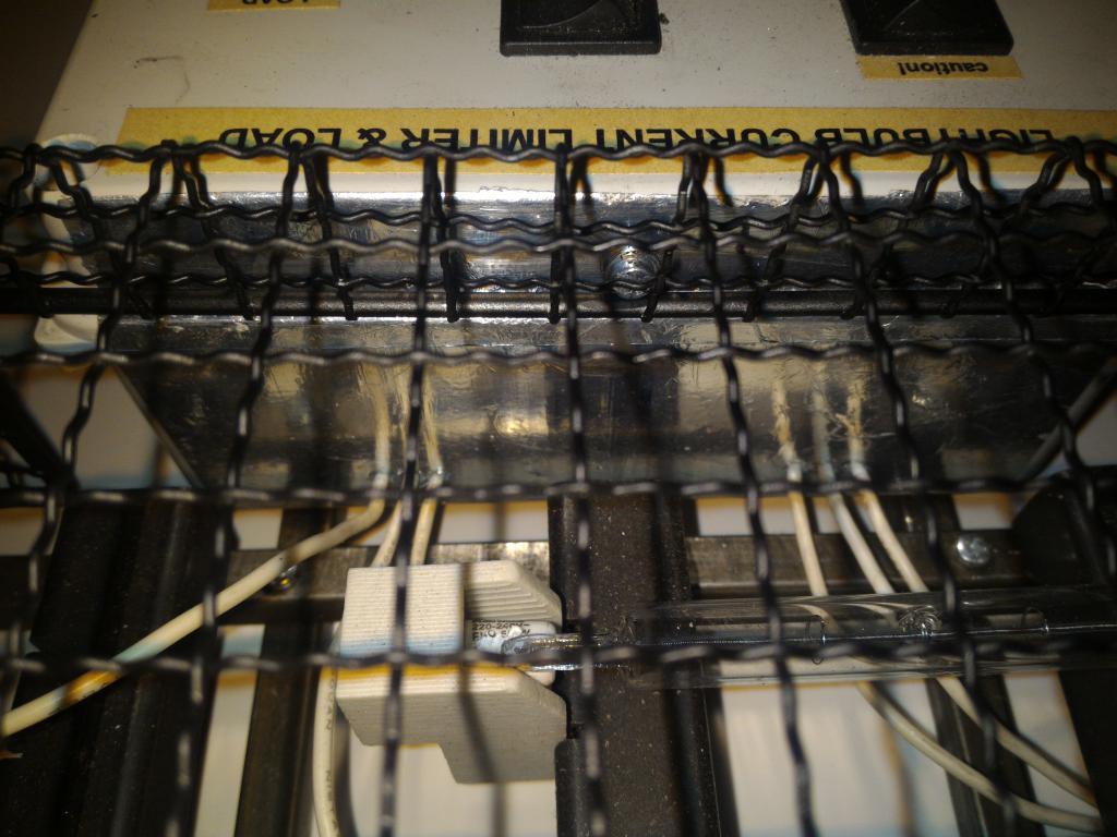
The lamps need mechanical protection, for avoiding damage during handling, transportation and storage. Like the low-power limiter, an off the shelf wire mesh frame was used.
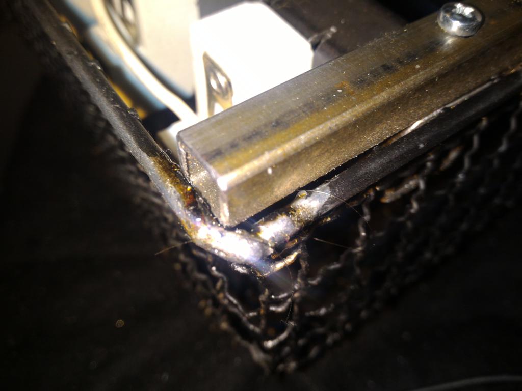
The wire was spot-welded in the lines along the bends and cuts. The cuts were perfrormed with a Dremel cutting wheel. The bends were assisted with partial cutting of the wires; this proved to be problematic, as it facilitated breaking of the wires in the bends. These breaks proved difficult to spot-weld. The post-bending joints also turned out to be problematic.
As the alternative, a copper-phosphorus brazing paste was used, and the
joints were flame-brazed. The fairly thin wires were easy to heat sufficiently
with a Dremel-class torch.
 wire cage, as bent and spotwelded | 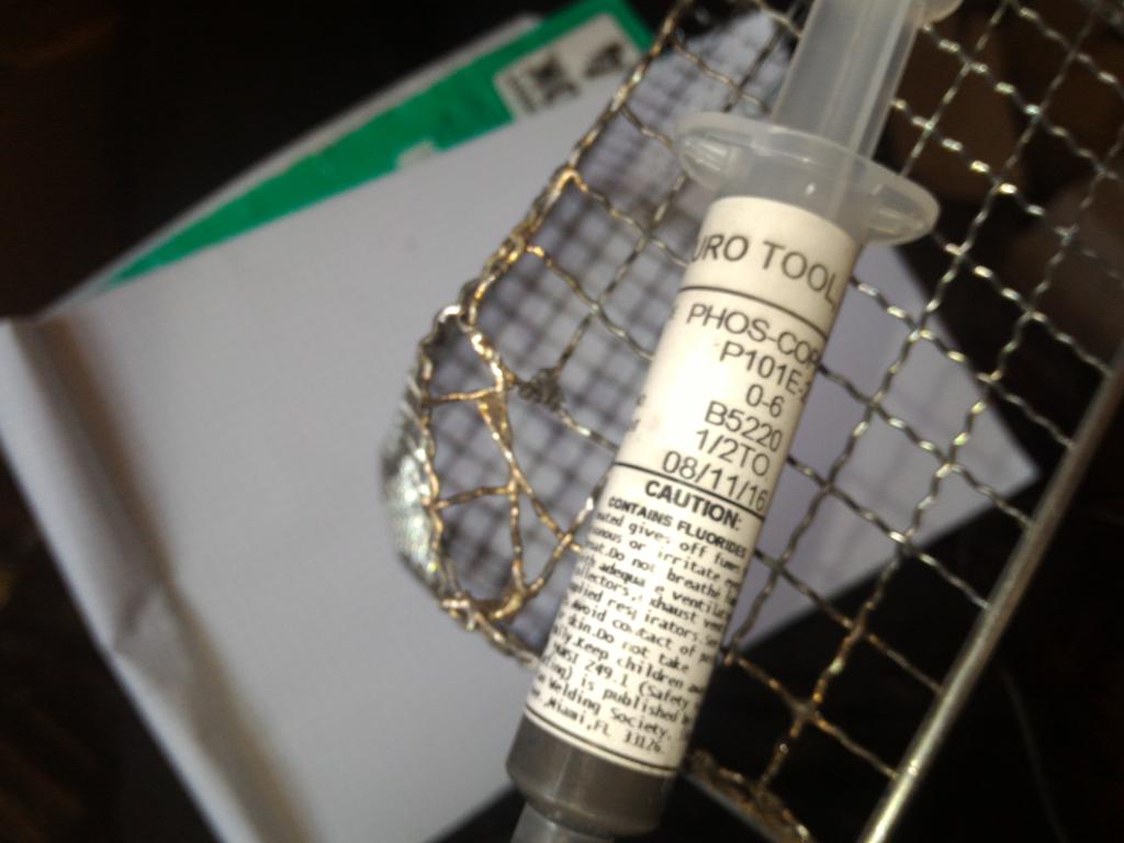 brazing paste | 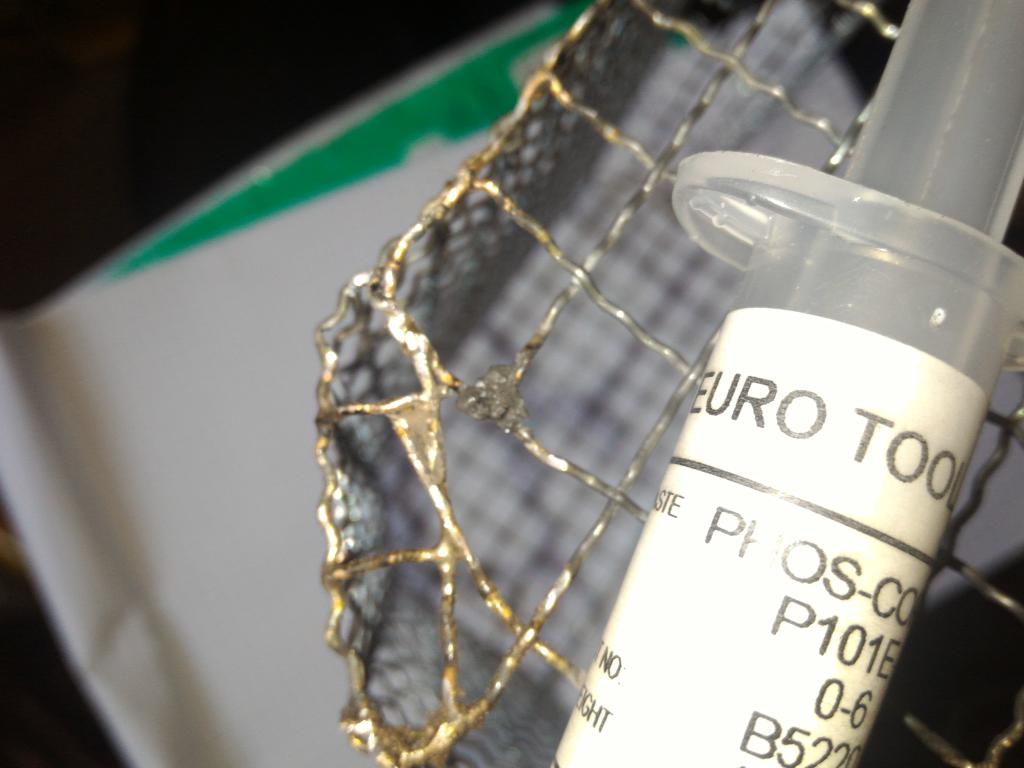 brazing paste | 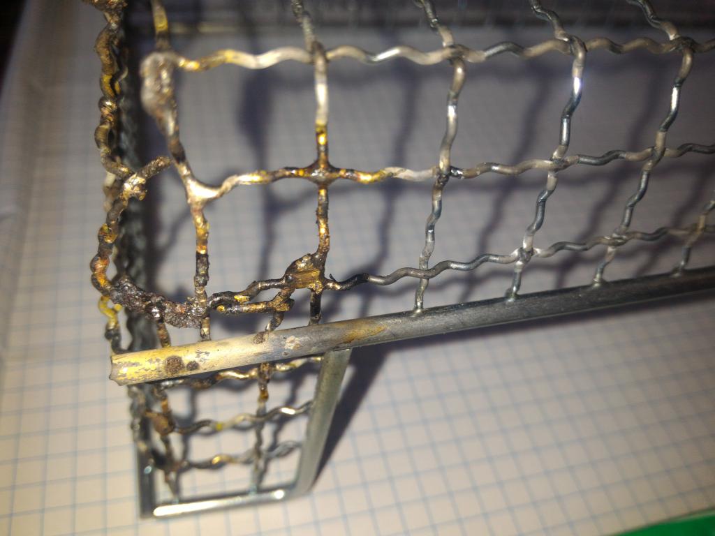 brazed joints |
 brazed joints | 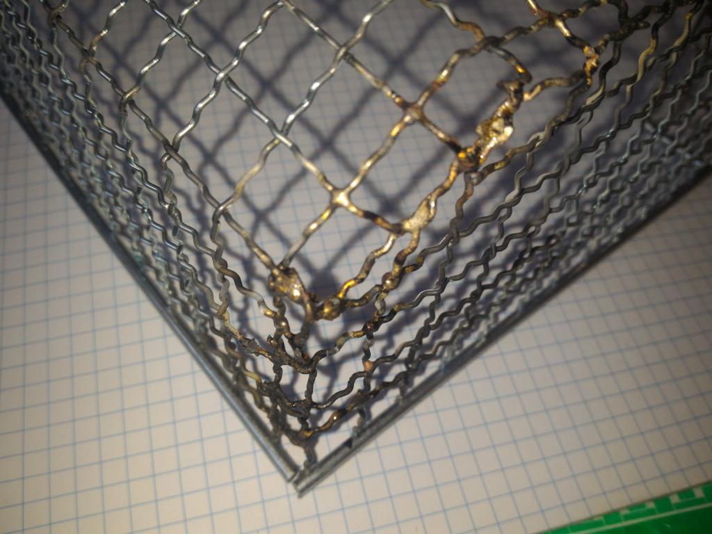 brazed joints | 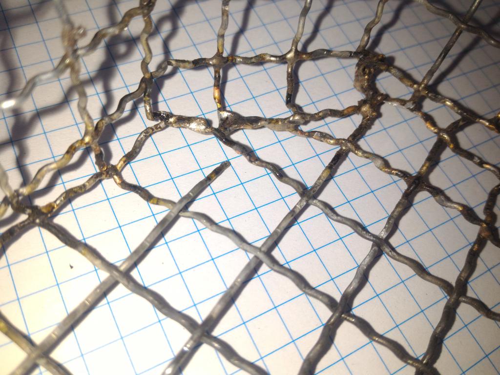 brazed joints | 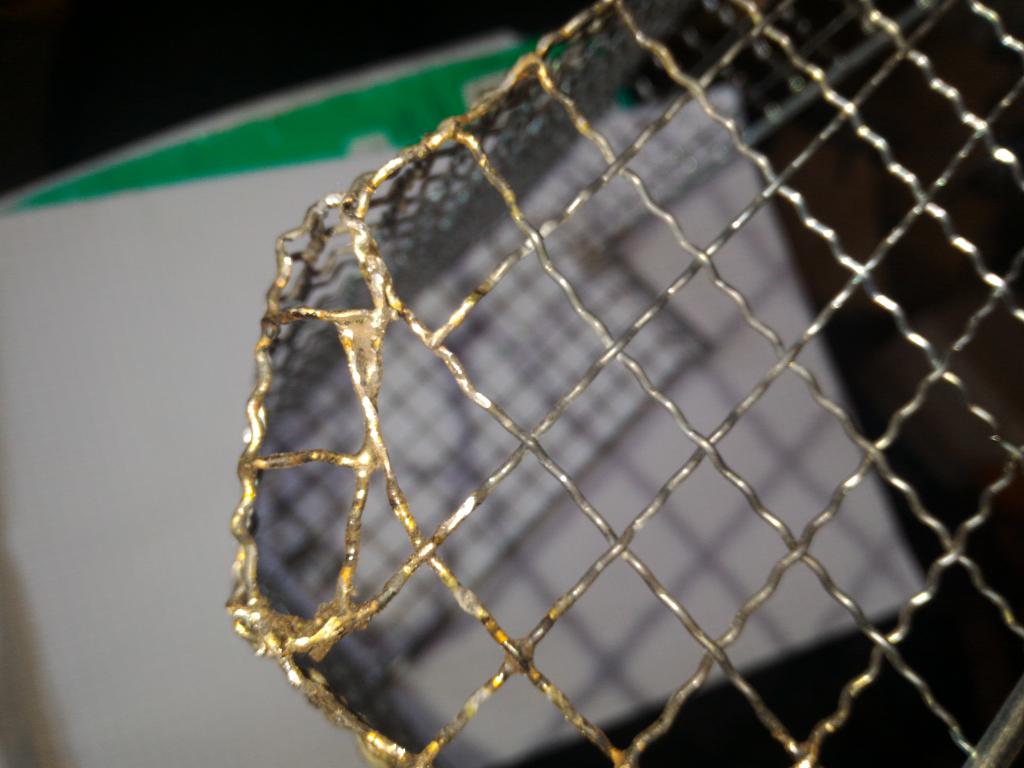 brazed joints |
 brazed joints | 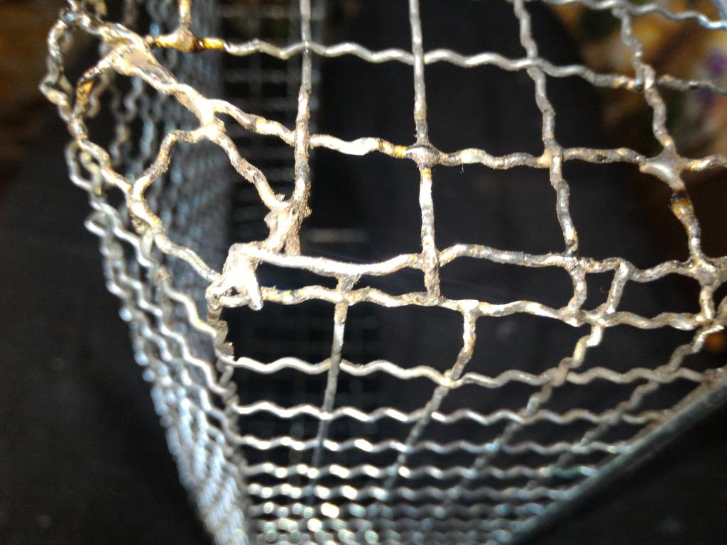 brazed joints | 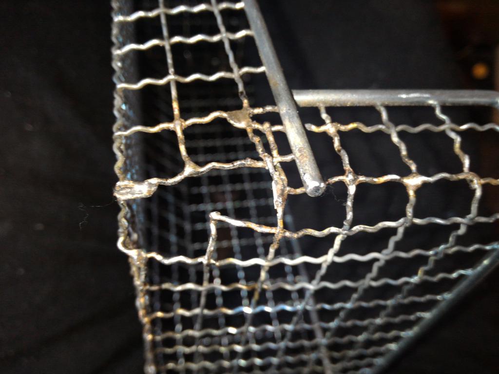 brazed joints | 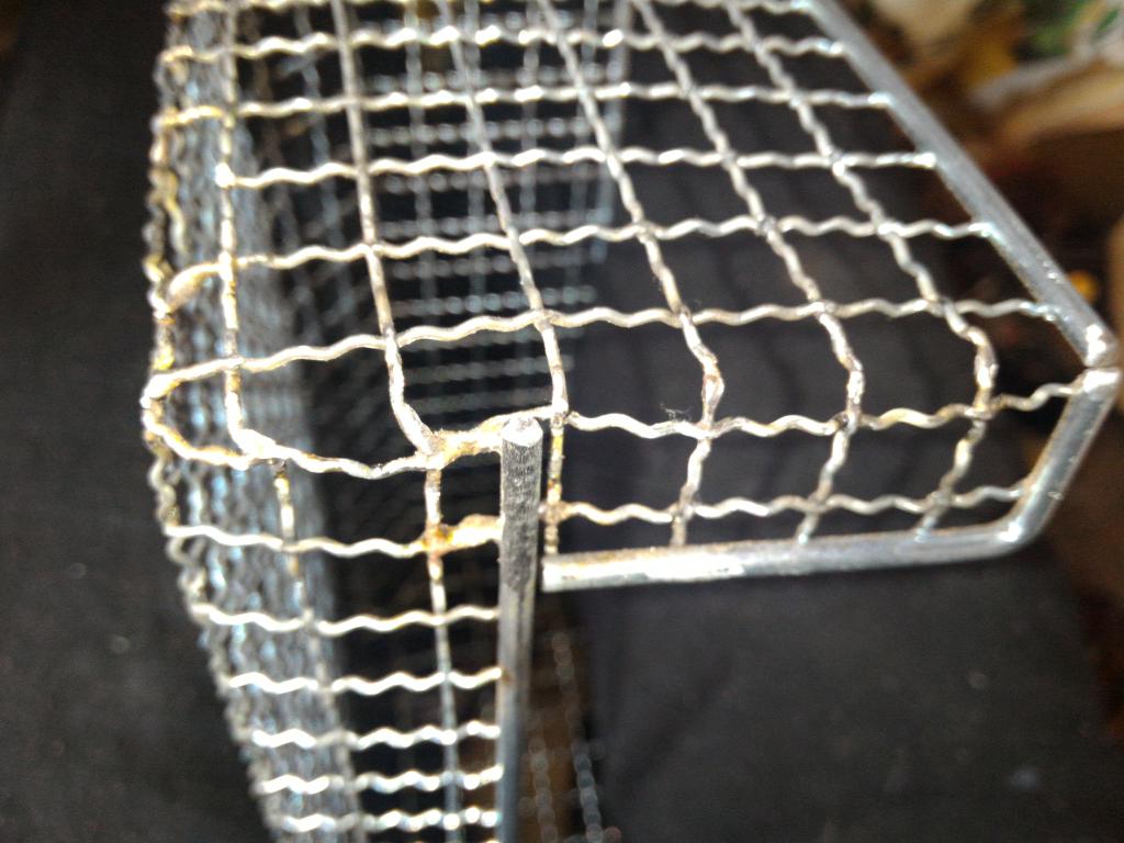 brazed joints |
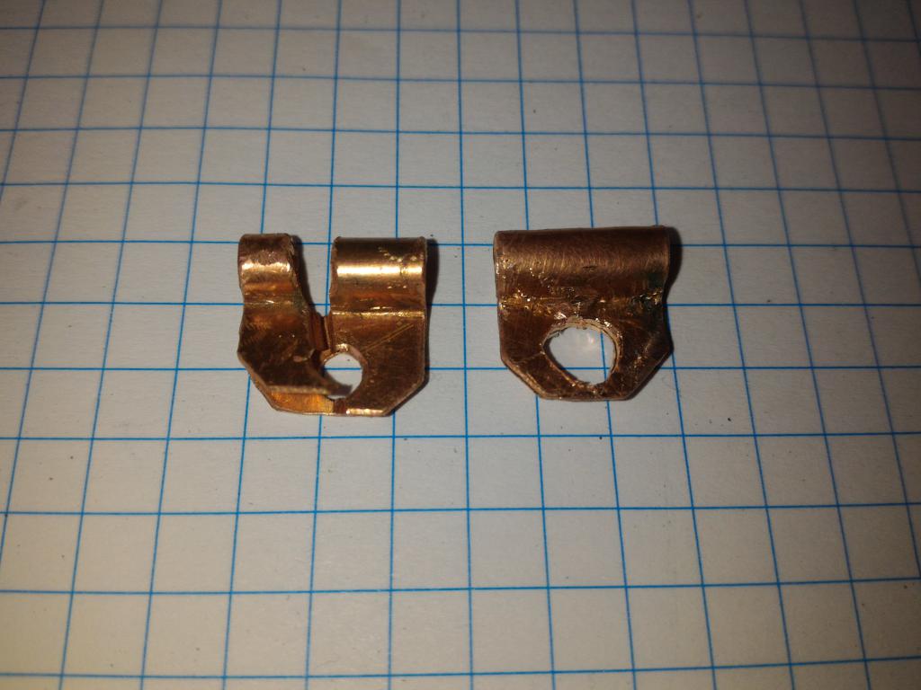
To facilitate opening and closing of the cage, hinges were needed. These were cut as strips of roofing-grade copper sheetmetal, and bent around a 3.2mm drill bit in a vise. One got a slit cut with a dremel wheel, to accommodate the cage wire. The hinges were attached with screws already in place.
 hinges | 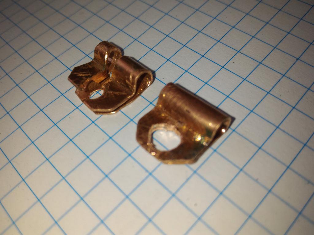 hinges | 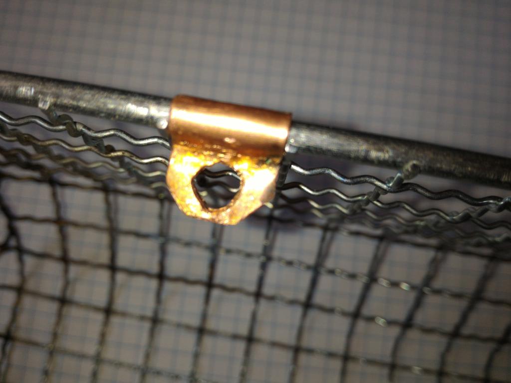 hinges | 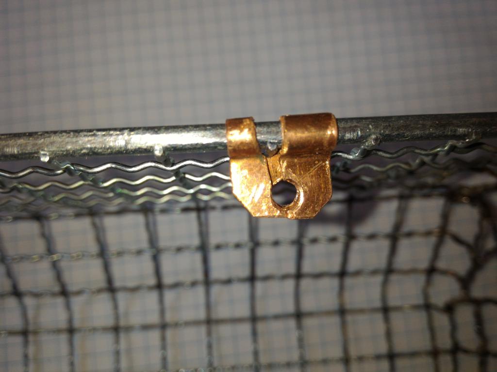 hinges |
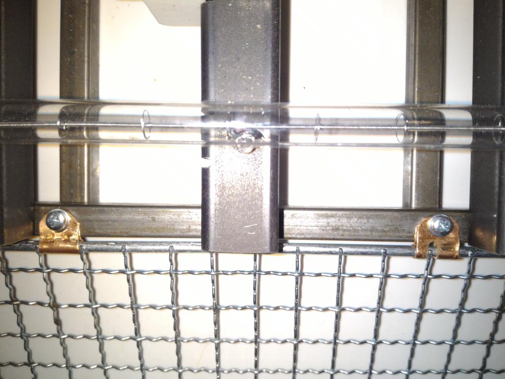 hinges | 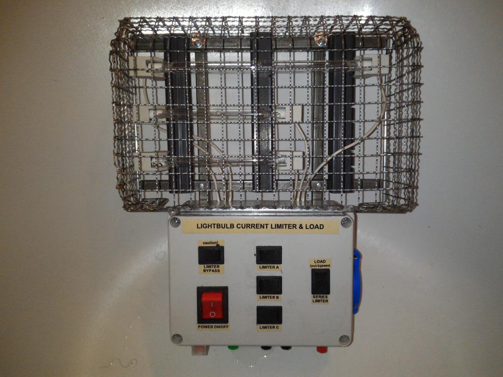 assembly | 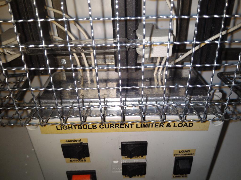 assembly | 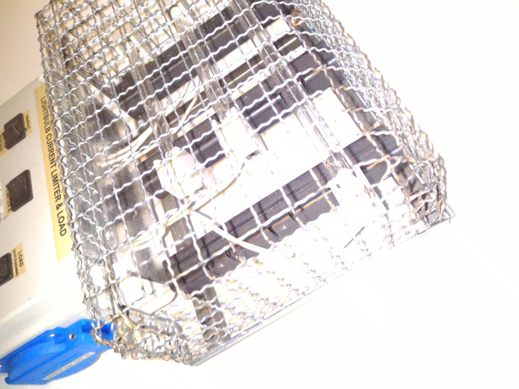 assembly |
The cage needs a lock to stay closed. A screw with a couple of washers was used, with the springiness of the cage frame used to open and close.
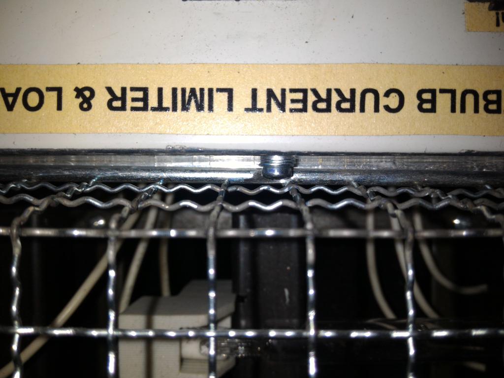 lock | 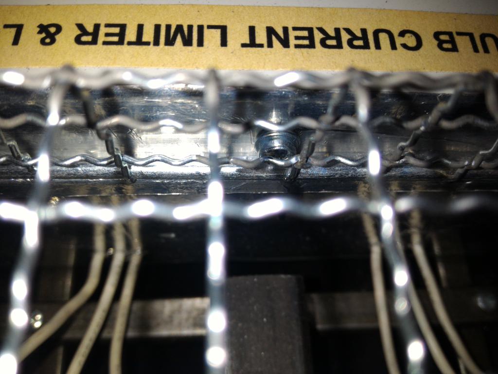 lock | 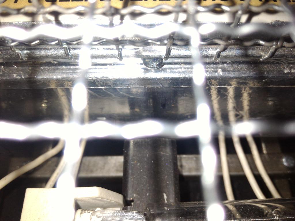 lock |
The thick frame rods had to be joined as well. This was done after assembling the cage and mounting it in place, to assure good fit to the bottom profiles. Lead-tin alloy was used, with amino acid flux and a torch.
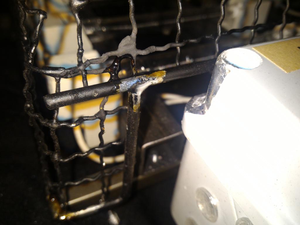 soldered joint | 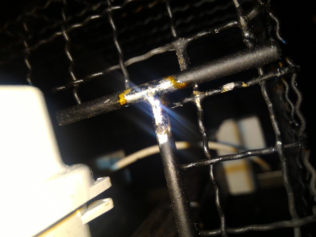 soldered joint | 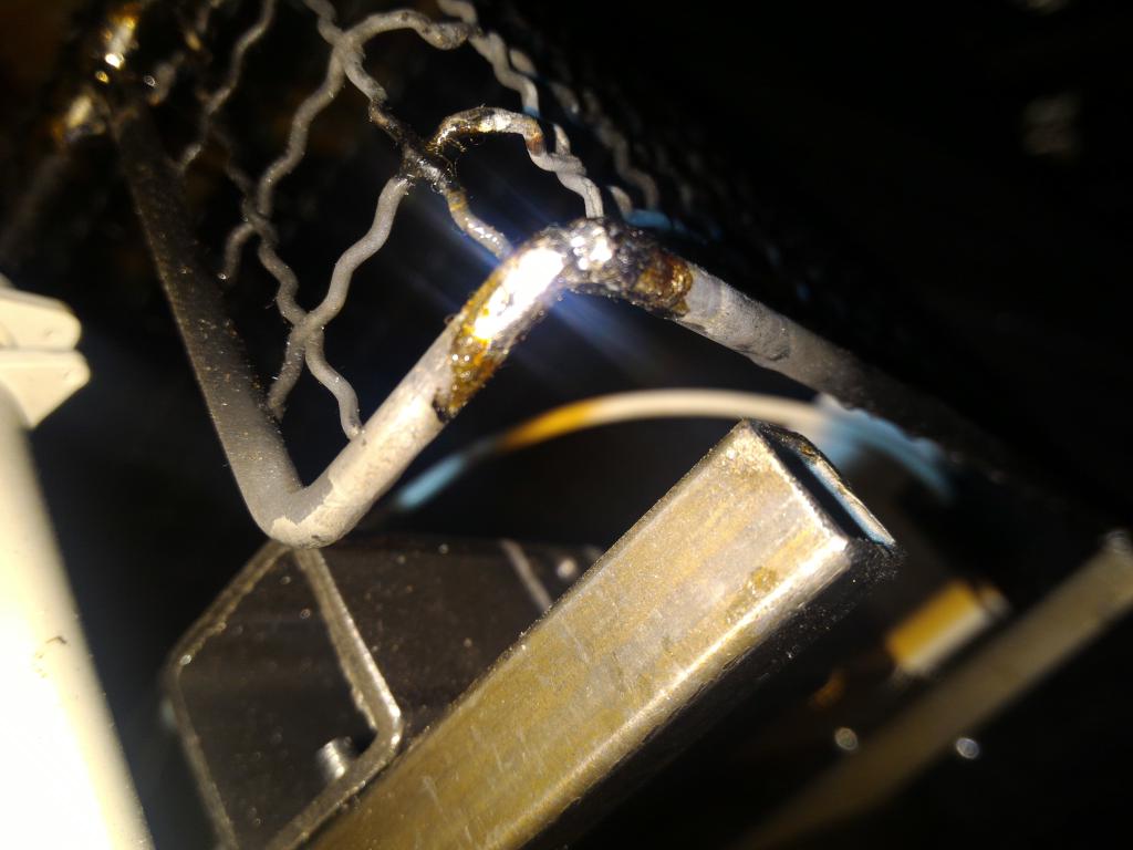 soldered joint | 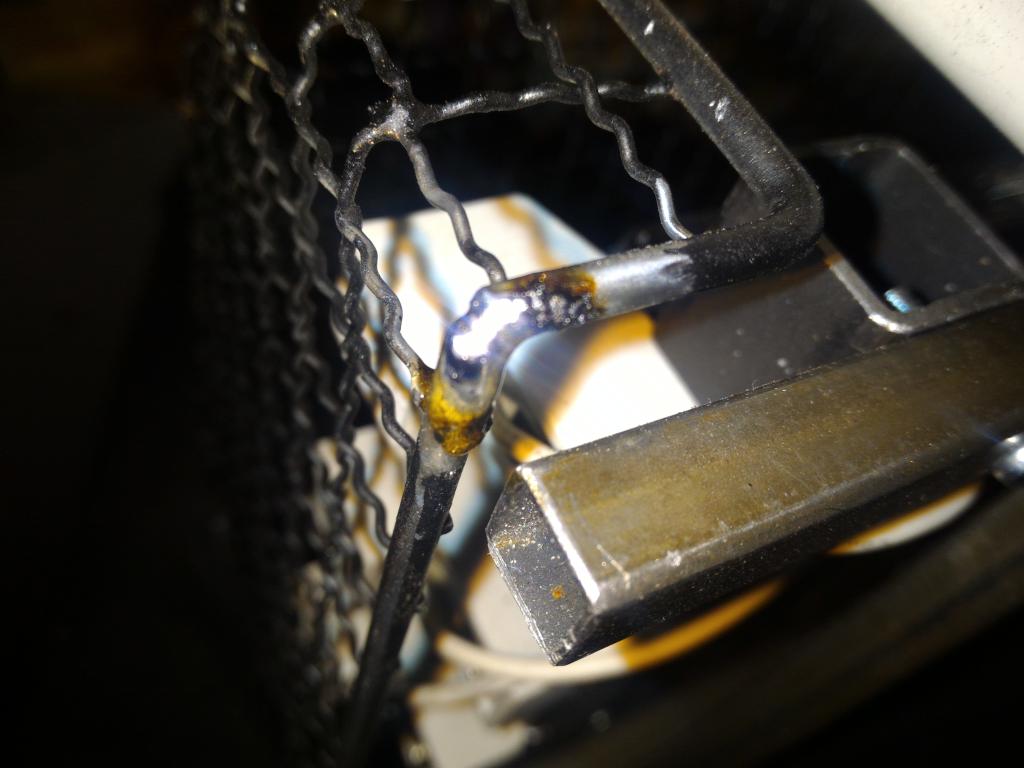 soldered joint |
 soldered joint | 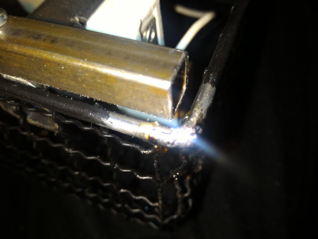 soldered joint |
The finalized cage was spray-painted matte black.
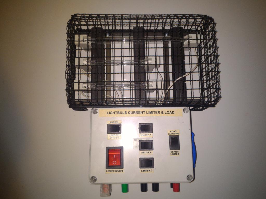 final assembly | 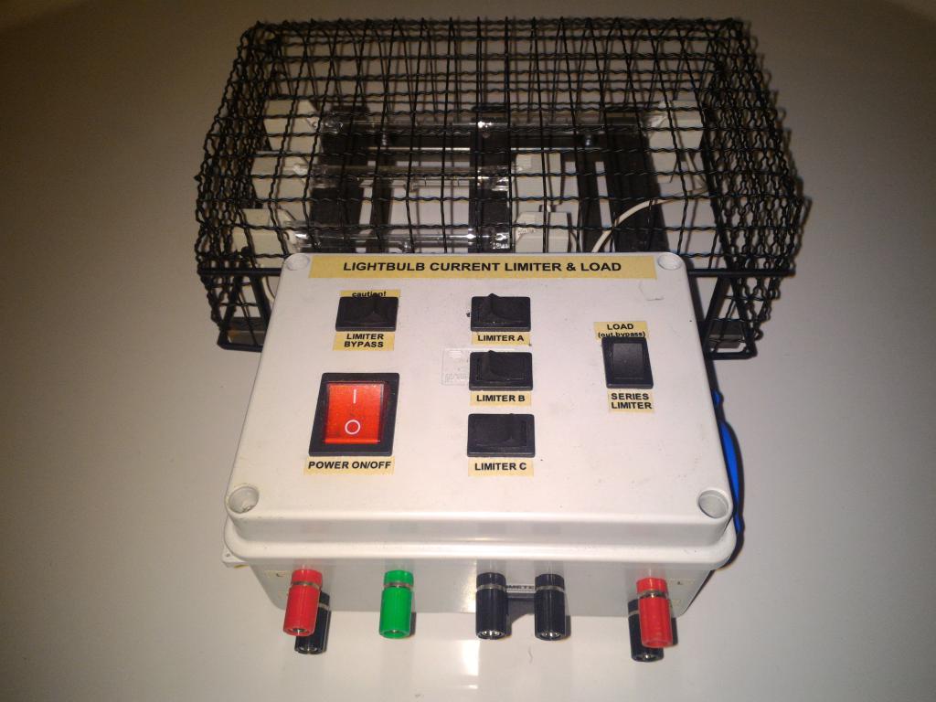 final assembly | 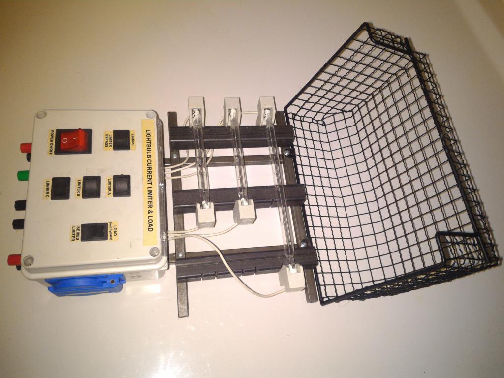 final assembly | final assembly |
 final assembly, lock | 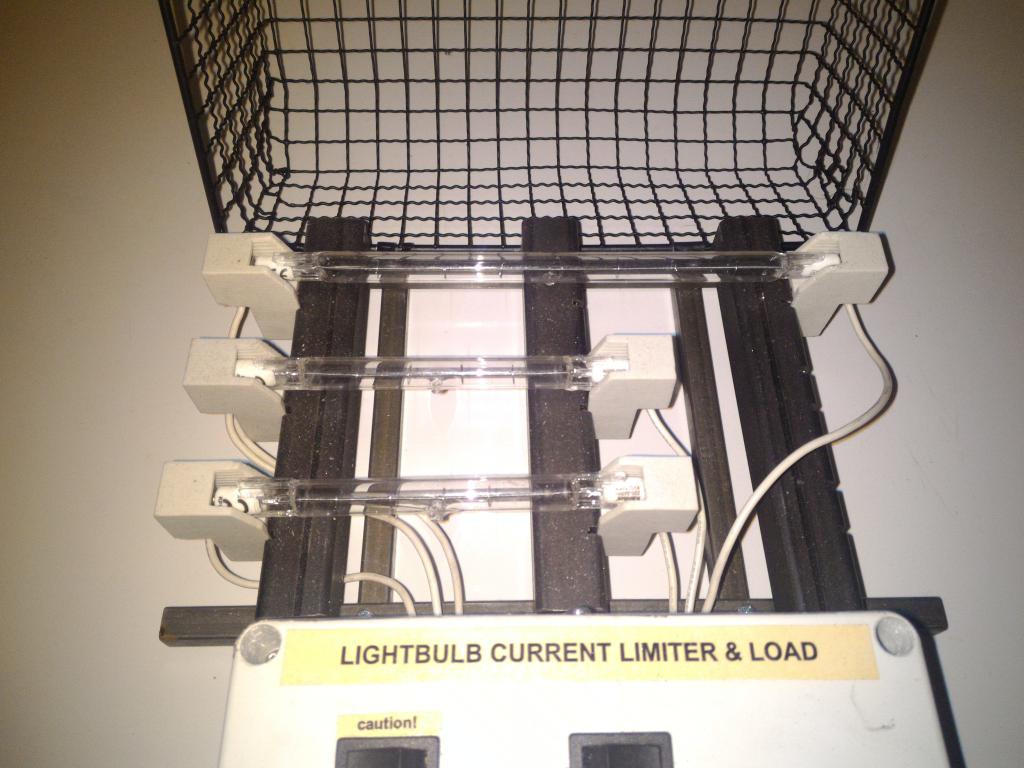 final assembly | 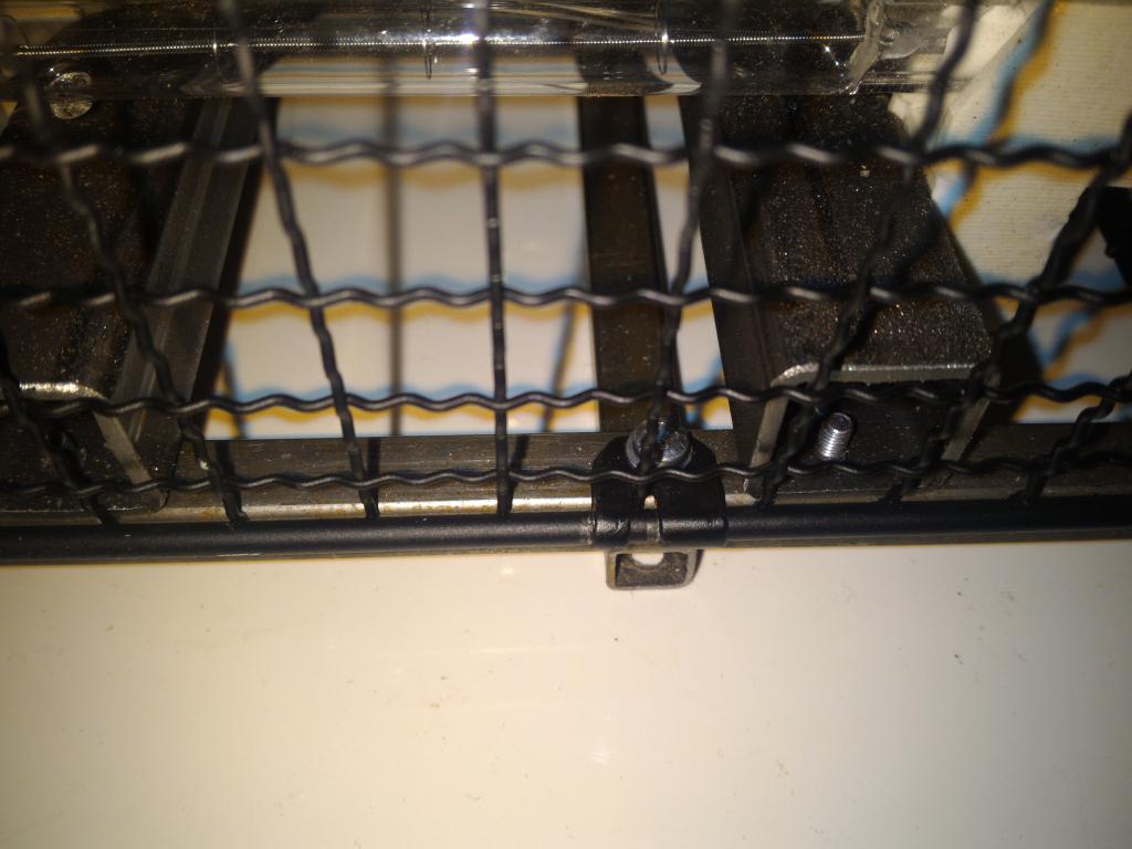 final assembly, hinges | 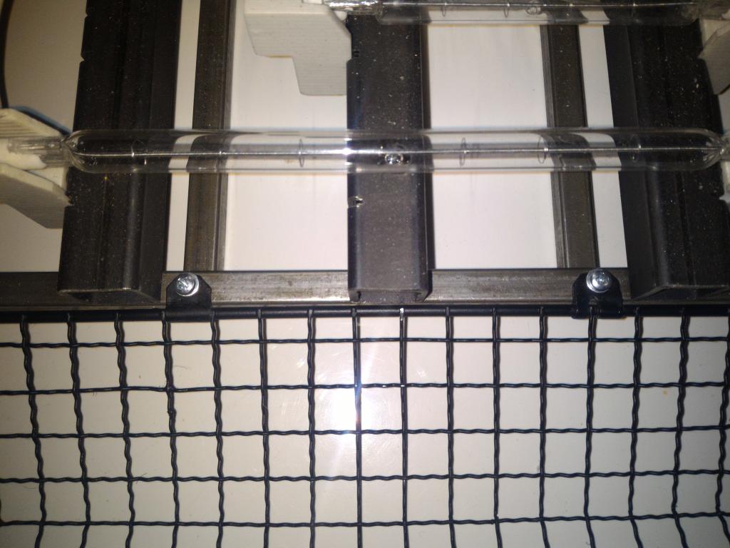 final assembly, hinges |
 final assembly, hinges | 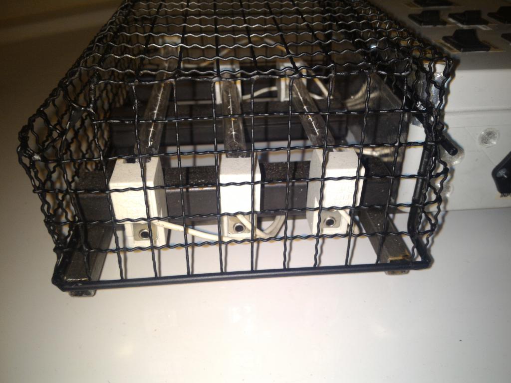 final assembly | 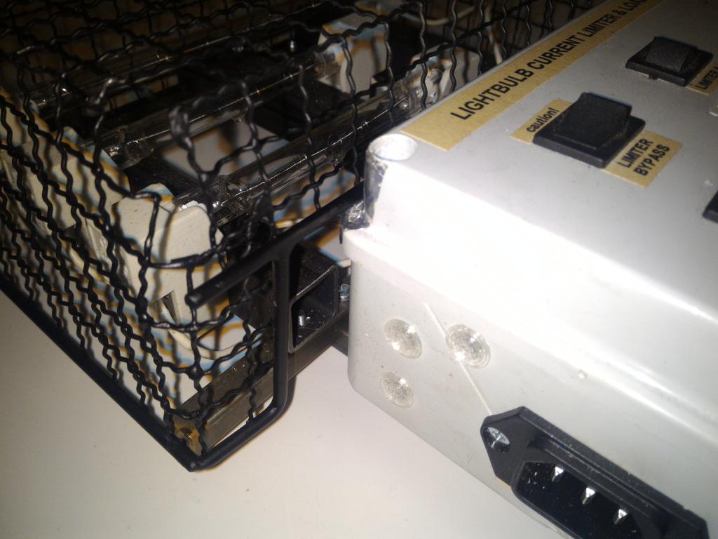 final assembly | 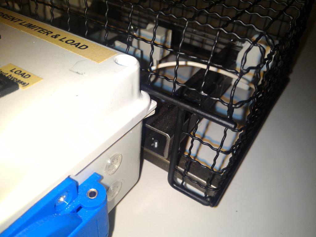 final assembly |
(todo)
At full power, the rig produces a copious amount of light and heat. The amount of light can be downright blinding. A shield may be needed.
The rig heats up fast. The lamps were run for only few dozens of seconds at time, so major issues were not encountered. The construction can however be expected to warm up considerably. A cooling fan may be needed.
The lamps may have to be mounted further away from the box to avoid heat damage. The cover will need to have an integrated heat reflector.
 - OpenSCAD file for panel cutouts, uncomment the desired panel to generate DXF
- OpenSCAD file for 3D-printable binding post hole plugs
- OpenSCAD file for panel cutouts, uncomment the desired panel to generate DXF
- OpenSCAD file for 3D-printable binding post hole plugs
DXF files for panel cutting (caveat, left and right have wrong holes for binding posts)