Sometimes materials need to be permanently joined. Sometimes epoxy is not an option for thermal resistance reasons or it hardens for too long, bolts or rivets or other methods are not usable as well, and the best way is welding. For those cases a spot welder is what the doctor may prescribe. A transformer from an old microwave oven has the right kind of the core and a suitable primary.
A broken microwave oven was acquired as a gift. The
microwave oven transformer (MOT) was
extracted. The secondary winding was removed by chiseling away its exposed sides and then
ramming out the chunks of wire packed into the core (that was the hard part of the work).
The pieces of iron between the primary and the secondary were left in place; they serve
as magnetic shunts, weakening the coupling between the primary and the secondary and
limiting the short-circuit current somewhat.
During the ramming-out operation, the transformer's primary was accidentally damaged with the
edge of the vise. It turned out that the Chinese used aluminium for the primary wires, as a
cost-saving measure. (Oh well.) As the nicks on the wire weren't too deep, it was decided to
attempt a repair. An aluminium solder (70% Sn, 30% Zn) and matching flux (containing
hydrofluoric acid) was used with a common soldering iron heated to a bit above 350 °C.
The nicks were filled with the solder, then the excess solder was filed away. The flux was washed
out of the transformer with hot water and dried. Transparent insulating plastic spray was then
used to cover the wires.
The secondary voltage was tested with five loops of wire. The output voltage in that configuration was found to be 4 volts.
The mounting base on the bottom of the transformer was cut along two sides, in order to allow the transformer to fit the case.
The secondary winding was intended to be made from a 16 mm2 welding cable. However the cable's thick rubber insulation did not allow more than three turns to fit, and even the third turn fit was unsuitably tight.
An alternative was therefore devised. Strands were isolated from a double-strand cable, 2x4 mm2, for connection of loudspeakers; the cables were cut longitudally and the strands pulled out. Two and two strands were twisted together and laid next to each other, then wrapped in a heat-shrink tube (pushing it through the tube was rather difficult towards the end). The resulting cable was of flat-ish profile (hence not twisting together all four strands) and allowed better fit in the core. The heat-shrink tube also provided much thinner insulation and therefore less wasted space and better cooling by the airflow and the thermal mass of the core.
Three turns were used for the secondary. There was enough space for fourth turn, but the cable was made too short for that and the fourth turn could impair airflow through the core. It could be added if needed, so 3-turn configuration, common for other such welders seen online, was chosen. The output voltage was about 2.4 volts.
Lugs were crimped to the ends of the cable, using a vise. A very large force was needed for satisfactorily firm fit. A heat-shrink tube then was pulled over the ends of the terminals.
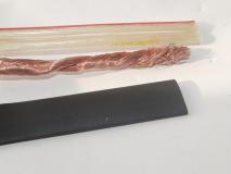 Primary cable, materials | 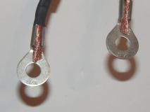 Primary cable, uncrimped lugs | 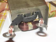 Primary winding in place | 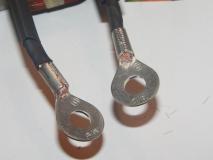 Primary winding, crimped lugs |
A case from a PC AT power supply was selected as a compact, heat-resistant portable housing. The transformer was mounted inside the case sideways, with primary side contacts on the mains side and secondary side lugs on the terminals side.
A cheap 12V fan was installed in its designated place in the case, with airflow aimed onto and through the transformer. The clearance between the fan and the transformer was rather low but sufficient.
A power connector was mounted in the appropriate hole in the case. An aluminium plate was installed over the other hole.
A carrying handle was mounted on the side of the case.
The case is connected to the safety ground terminal of the power socket.
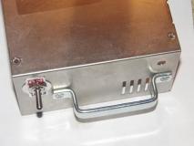 Box with main switch | 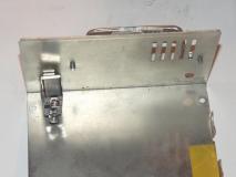 Box with main switch, inside | 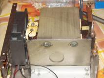 MOT in a box, fitted | 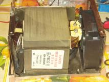 MOT in a box, other side |
The case terminals were made from 8 mm diameter solid copper rods. A M8 thread was cut into the copper (that was pretty hard work). A slit was cut into one end of each of the terminals, to allow turning it in a nut with a screwdriver. Brass nuts were used for attaching the terminals to the case.
The right terminal was connected directly to the (grounded) case. No electrical insulation was needed here. A secondary lug was connected to the terminal via the brass nut.
The left terminal had to be insulated from the case. Three-piece sandwich of fiber-plastic composite, salvaged from an old depopulated circuitboard (cut and filed into shape, with the copper traces filed away, the middle plate filed down to thickness matching the case metal) was made to fit one of the output wire cabling cutouts in the case. The terminal was attached to the other lug of the secondary in the inside.
Brass nuts are used for both the terminals, to facilitate better electrical conductivity and lower the ohmic heating and power losses.
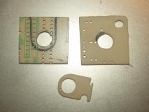 Output terminal insulation parts | 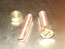 Output terminals | 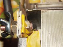 Isolated terminal | 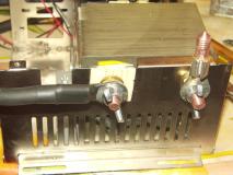 Isolated and grounded terminal |
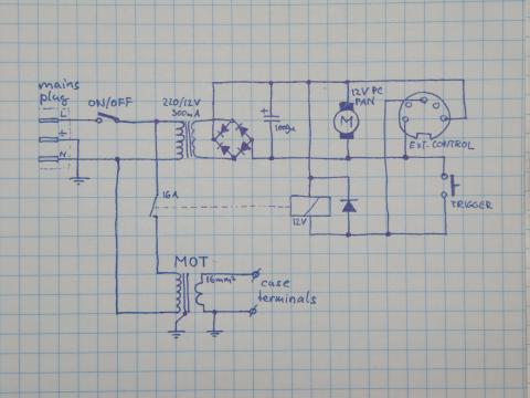
The unit has its own power supply. A small wall-wart was cannibalized for the transformer and the diode bridge and output smoothing capacitor (it was a cheaper way than making it from parts). A 12V/300mA power supply was chosen on the price/parameters combination.
The power for the main transformer is controlled with a 12-volt relay rated for switching 16 amps, salvaged from another microwave oven.
The main switch, 250V/16A, is the main power switch. It switches on the 12V transformer, which powers the fan and the relay circuit.
The main switch has two on-positions. The top one connects the electronics directly to the mains. The bottom one puts an inrush current protection thermistor in the series. It was experimentally determined that with such added variable resistance (the thermistor quickly becomes more conductive as it heats up) the likelihood of tripping the breakers is much lower. The hypothesis is that the thermistor reduces the inrush current when the remanent magnetization of the core from the previous weld is in non-favorable direction and the mains power is at the wrong phase when the relay fires.
The small red-tipped button controls the relay circuit. When pressed, the relay switches on.
The 12V power, the relay input, and the ground are connected to the 5-pin DIN connector on the front panel. The leftmost pin, viewed from the outside, is ground, the center pin is the relay input, the rightmost pin is 12 volts. The relay switches when the relay input is connected to the ground. The connector is intended to be used for attaching an external switch, whether on a welding tool holder or as a foot switch.
The low-voltage electronics is not connected to the case nor any other part of the circuit.
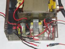 Control unit | 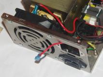 Control unit, another view | 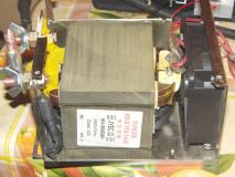 High power side of the assembly | 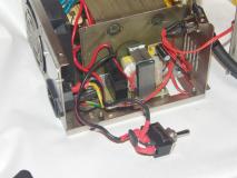 Thermistor connection |
The welding electrodes were made from 8mm thick copper rods, same as the terminals. They were filed into tips on one side with a power drill and a file. The other side had a M8 thread cut, to facilitate attaching it into some sort of a holder, and a slit cut for a screwdriver.
The stationary electrode holder was made from a 25mm2 cable lug. The cable end of the lug was gently hammered into the right side, a 7mm hole was drilled along through it, and a M8 thread was cut in it. The electrode then was screwed in and tightened. The holder is attached to the right, case-connected terminal with a wingnut.
The moving electrode holder was made from a prefab steel part, L-shaped with holes, designed for assisting with joining wood. A hole was drilled for the electrode. For moving the electrode, the holder was attached via a hinge. The hinge was directly connected to the case, so the interface between the holder and the hinge had to be insulated. A layer of plastic composite, same material for insulating plate for the left terminal, was placed between the hinge and the holder. Two M3 screws with insulating washers under their heads (the same kind as for insulated mounting of the TO220 casings) were used for joining the hinge to the holder.
The moving electrode was connected to the left terminal with a length of a 25mm2 welding wire with lugs crimped to their ends. A cast-iron vise was broken during crimping, as the force needed was a bit too much and the vise cracked in tension. The cable was still a little loose in the lug; a center punch and a hammer were able to deliver enough force to locally deform the crimping sheath and achieve a tight fit.
The moving electrode holder turned out to be clumsy, get in a way when welding in tighter spots, and quite fast get uncomfortably hot. A modification was therefore devised; the excess material was cut from around the electrode mounting hole and a small block of wood was attached to the holder as a makeshift handle and thermal insulation for the operator's hand.
For access to tighter spaces, one or both electrodes can be hand-held.
Attempt was made to design an electrode holder from combination pliers. Attempt to drill holes into the pliers was unsuccessful due to the hardness of the metal. Holders were therefore attached to the pliers with epoxy, but the epoxy tended to fail in tension when pressure was applied to the electrodes.
Some assemblies require the operator to have three or more hands. To reduce the hassle with at least the trigger switch, and lower the number of missing hands by one, a foot switch was devised. A spare block of wood was used as a mounting substrate. A piece of iron sheet was used as the pedal. The hinge and spring to keep it in elevated position was made from a tin-can thin sheetmetal, affixed to the thick iron sheet by the means of resistance soldering. (The attempt to spot-weld it failed.) A solder wire was placed between the thick and thin metal and current was run through them, heating the area and melting the solder. The pressure of the electrodes assured good contact between the metals while the solder solidified. The technique is similar to resistance brazing, except the temperature is lower and the alloy is different; standard Sn37Pb alloy was used here, screw RoHS.
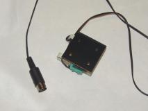 Foot switch | 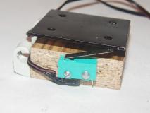 Foot switch, front view | 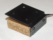 Foot switch, back view and hinge | 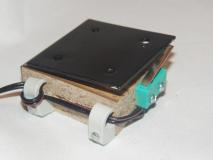 Foot switch, side view |
The welder's power is fairly good. A thin iron sheet, salvaged from tin cans, can be welded with ease and the metal does not tend to fail in the joint. Thin iron can be also welded to thicker iron (e.g. tin can sheet onto a thick washer). Thicker metal is increasingly problematic, requires long heating time and high pressure from the electrodes; the electrodes and their holders also become uncomfortably hot quickly. Two M3 washers can be welded together. M4 washers aren't so easy and the weld tends to fail; more testing will have to be done with electrodes capable of higher clamp force. Heat-treated spring steel sheet can be welded to other metal, with only localized heat-induced loss of properties; flat springs can therefore be affixed to other parts. A thin sheetmetal can be welded to a M4 nut, however the weld will fail under higher forces.
Copper sheets can not be welded together as the thermal conductivity will not allow localized-enough heating. Thin copper wire can however be attached to iron.
Spot-welding of wire grid for the cage for lightbulb in the Lightbulb Limiter
turned out to have a very satisfying performance. The wires heated well between the electrodes
and stuck together easily when subjected to moderate pressure. The electrode holder design however
caused accessibility problems in some locations of the cage and a handheld electrode had to be used.
On a 10-amp 230V circuit, shared with a fridge, the welder occasionally tripped the breaker when the fridge was operating. A NTC thermistor rated to 20 ohm/5 amps (the Lightbulb Limiter switched in a thermistor-only configuration) eliminated this issue, for not-really-perceptible loss of welder's power.
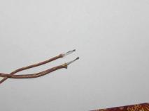
The welder was successfully tested on Type K thermocouple wire. The wire used was 0.25 mm diameter (AWG 30 gauge),
sourced originally as a thermocouple from Sparkfun.com (link).
Welding of such thin wire requires care and fairly short welding times. Copper-tip electrodes were used.
The wire occasionally stuck to the electrodes but it was fairly easily torn off, without the weld giving way
(usually). Mild pulling force was used to test the weld integrity. The resulting thermocouples were tested
at room temperature and in warm tea and gave the same results as the original one.
 Welded thermocouples | 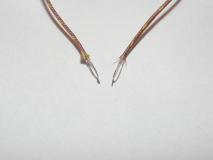 Welded thermocouples | 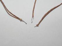 Welded thermocouples, original at right | 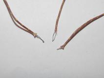 Welded thermocouples, original at right |
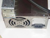 Back of the unit | 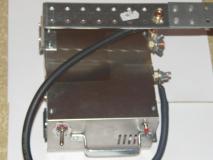 Top of the unit | 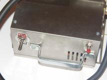 Side of the unit, carrying handle | 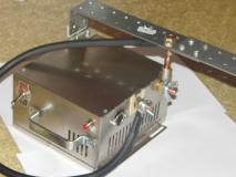 Edge view of the unit |
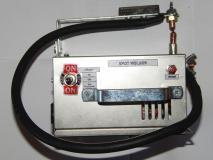 Spot welder, side panel | 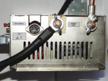 Spot welder, output side | 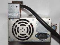 Spot welder, power feed side |
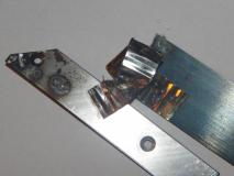 Test welds | 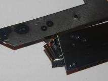 Test welds | 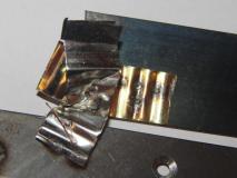 Test welds | 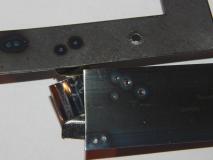 Test welds |
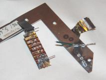 Test welds, zinc-plated wire to thick metal (notice the white spots of zinc oxide from burned coating) | 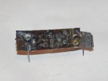 Test welds, zinc-plated wire to thin sheetmetal |
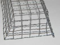 Lightbulb cage welds, right side | 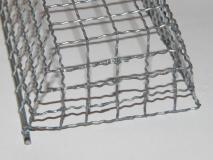 Lightbulb cage welds, left side | 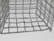 Lightbulb cage welds, left inner side | 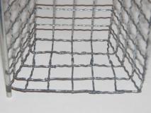 Lightbulb cage welds, right inner side |
Try out resistance brazing.