Often it is necessary to keep some material at elevated temperature - whether it is
molten chocolate, polycaprolactone pellets for processing, or nickel-plating bath.
A water bath is called for here.
A very simple approach was chosen, on the basis that it is better to have a simple single-temperature water bath good enough for most purposes than to not have a state-of-the-art regulated one.
As a temperature-control device a snap-ring bimetal electromechanical thermostat module was chosen, with switching temperature at 90°C and maximum switching current of 10 amps.
For the bath itself, an electric kettle was salvaged
from electronic waste bin in a local shop. The lid was missing and the switch assembly
was mechanically damaged, the heating element, as hoped for, turned out to be intact.
(An electronics-regulated version was planned, but the amount of round tuits
required was a bit too high; it is better to have a decent thermostat than to not have a
perfect one.)
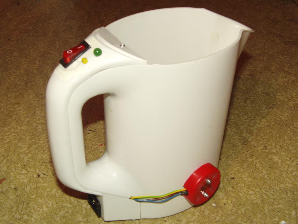
The kettle was first taken apart.
 Kettle, heater view | 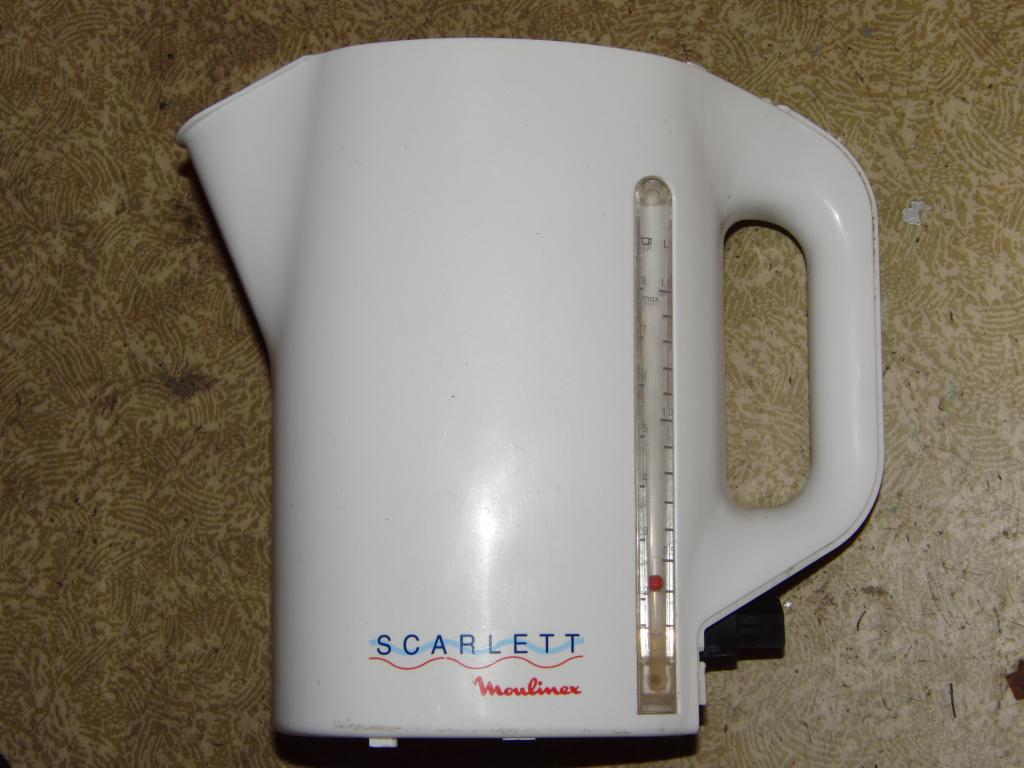 Kettle, side view |
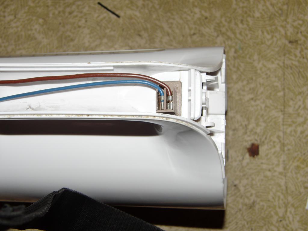
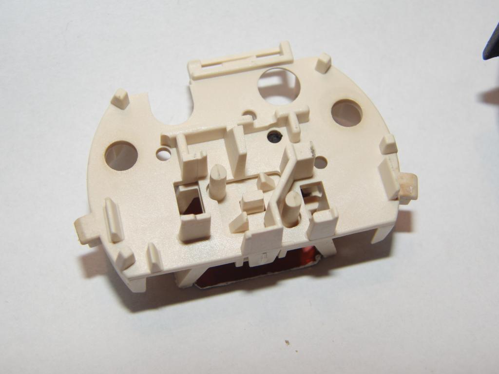
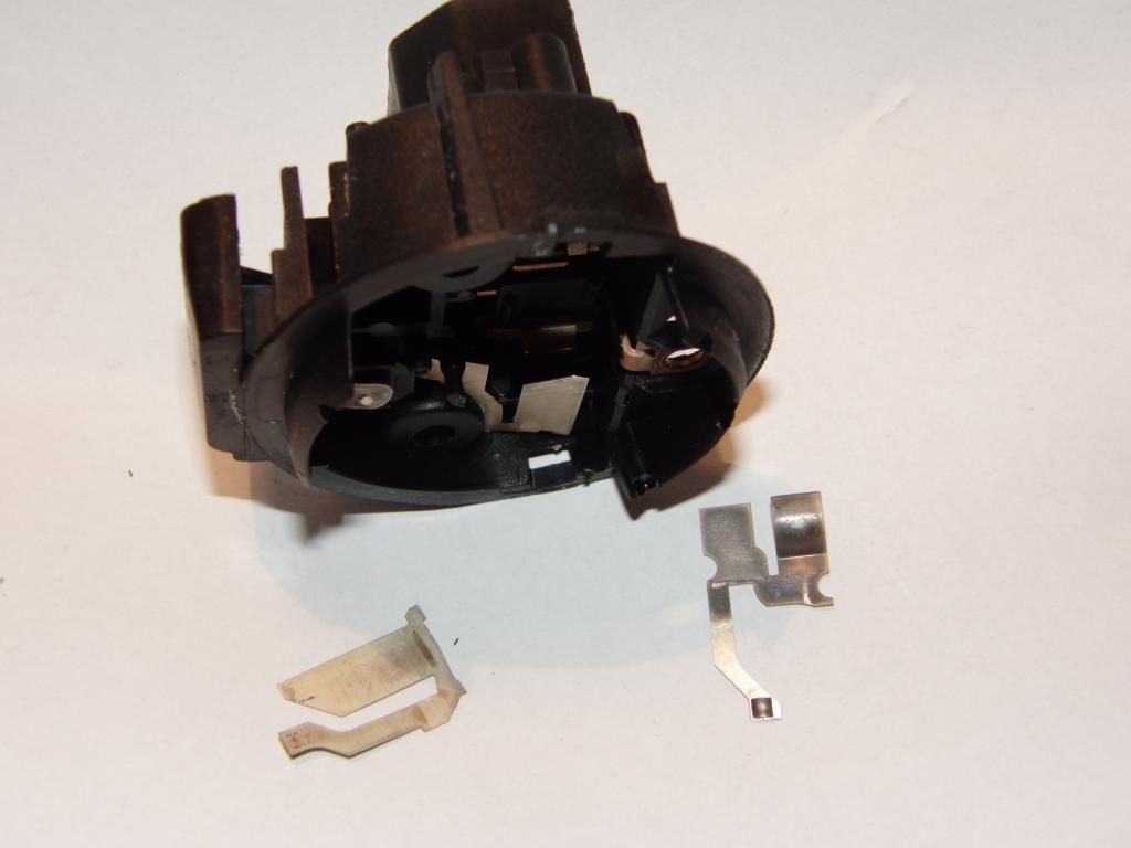
The power switch was integrated in the top end of the handle. A passage for steam
was connecting the switch with the area above the water, allowing the steam to flow
to the switch assembly, which contains a bimetallic strip that the steam heats up (probably
by condensing on it, as the phase change heat is significant), the strip deforms and
disengages the switch and powers off the kettle.
 Kettle, switch | 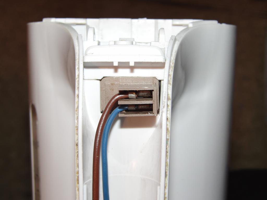 Kettle, switch | 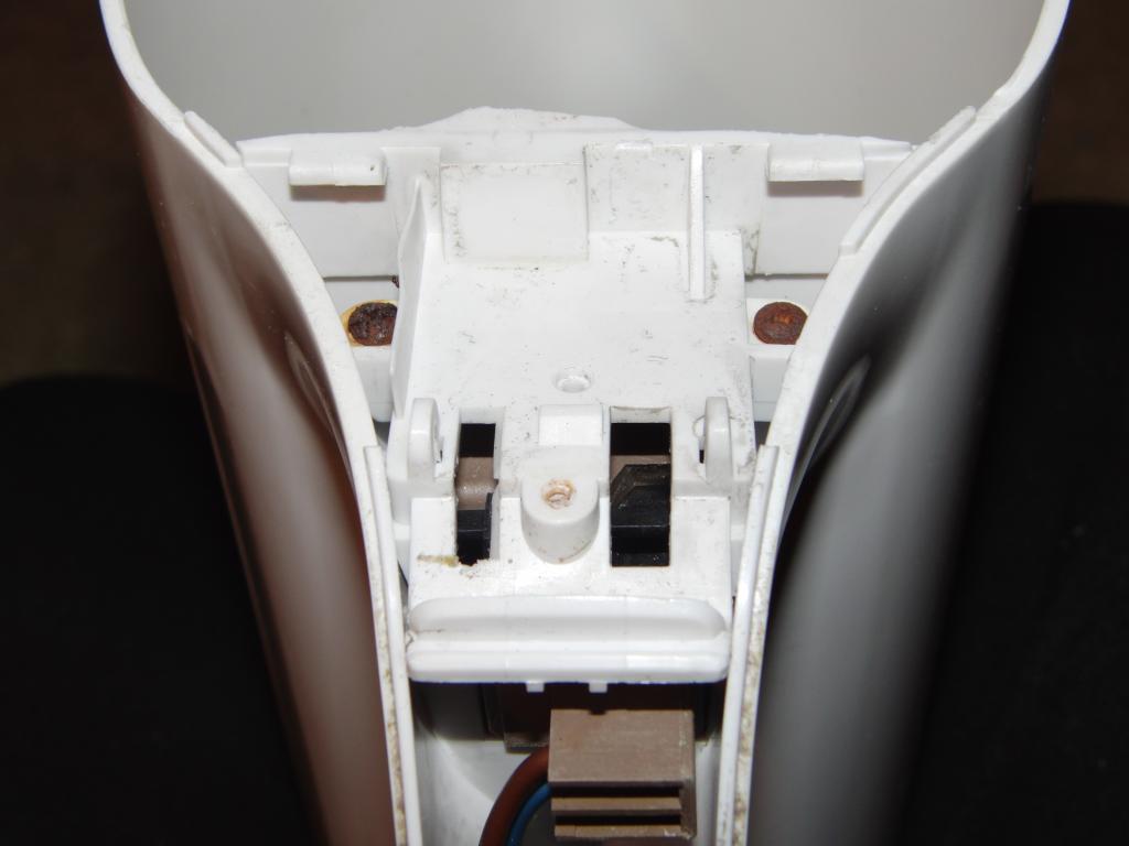 Kettle, switch mount | 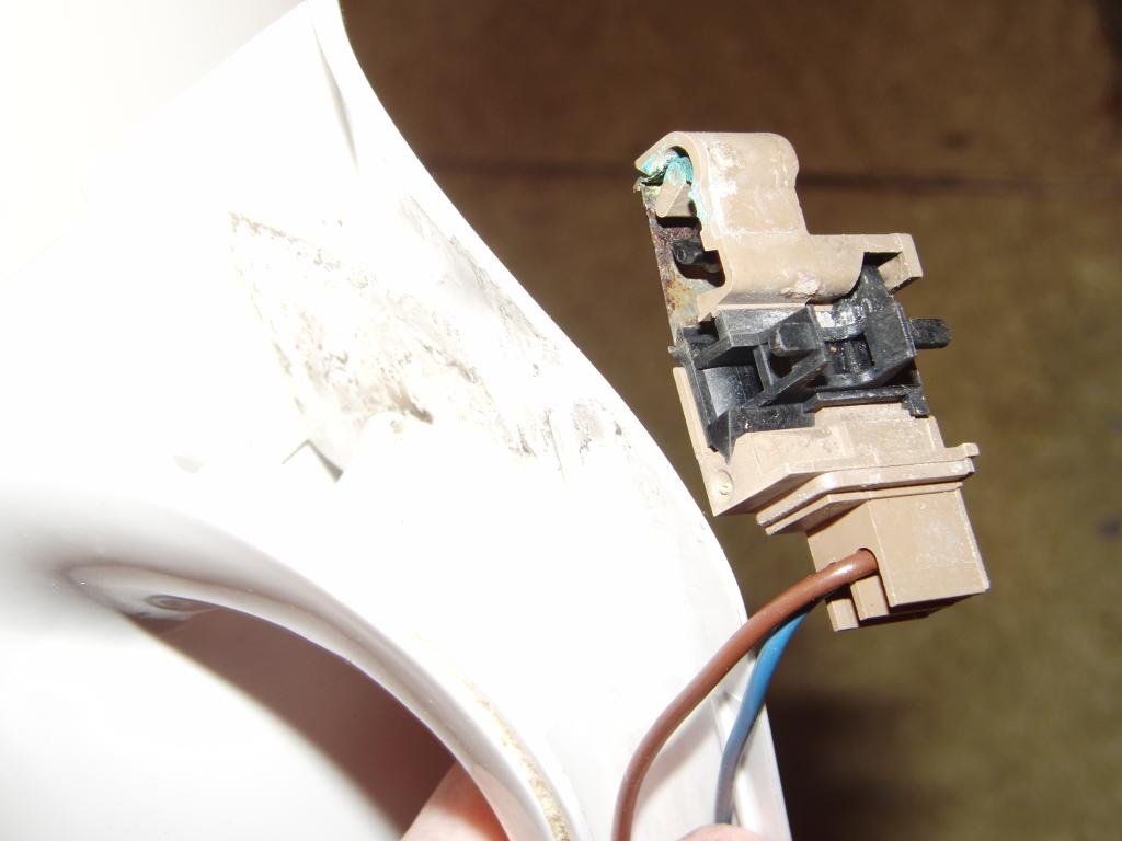 Kettle switch, corroded bimetal strip visible |
 Kettle switch, corroded bimetal strip visible | 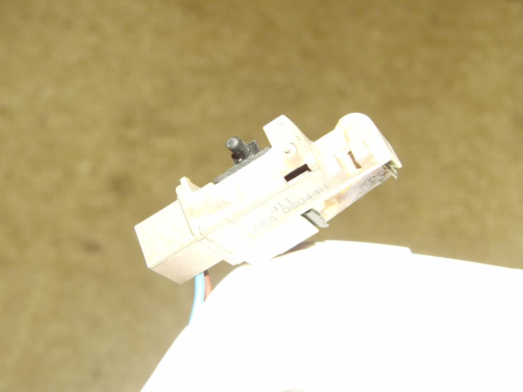 Kettle switch |
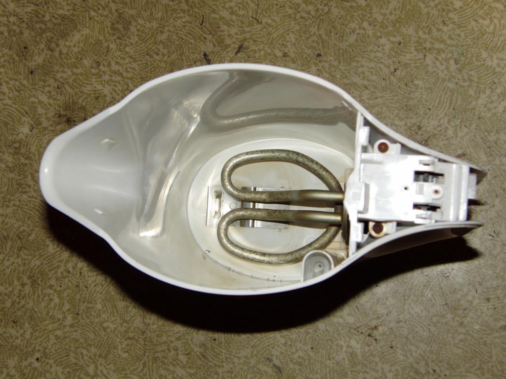
The heating element was sealed with a rubber gasket and kept in place by compression via the thermoset plastic housing of the power connector. The connection between the heater and the power leads was found to be done via a pair of springy metal contacts.
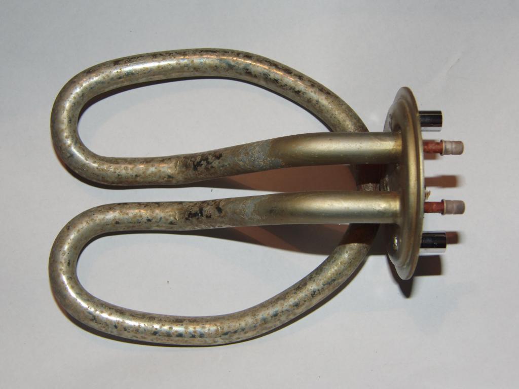 Heater element | 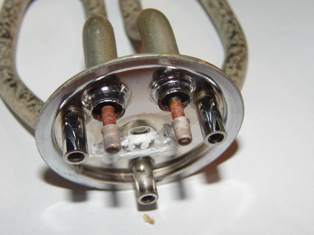 Heater contacts | 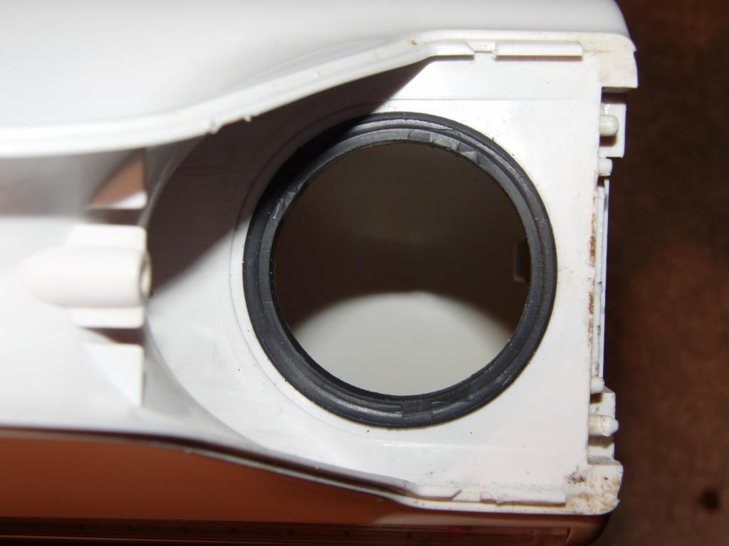 Heater gasket | 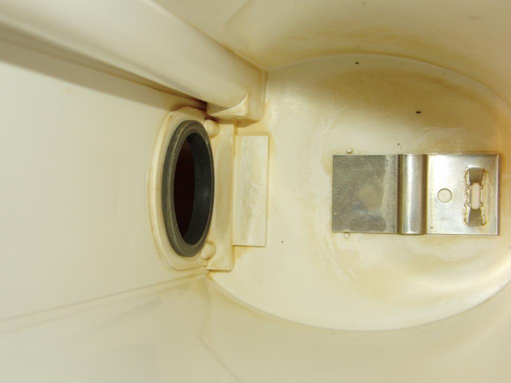 Heater gasket |
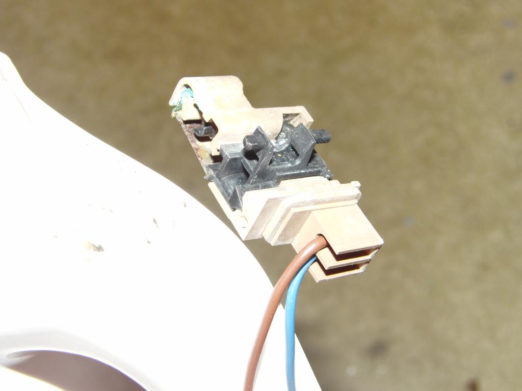
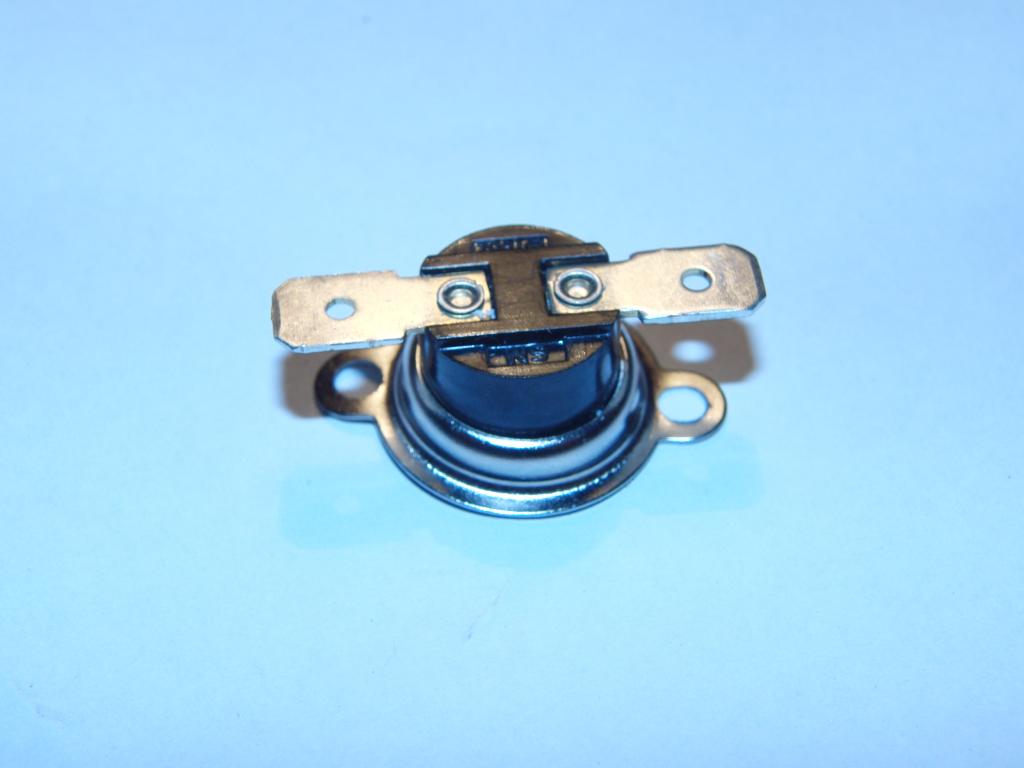
The connector housing was found to contain spring-like contacts and a pusher assembly
with a bimetallic strip snap-ring, thermally coupled to the body of the heater. This apparently
acts as a reversible thermal cutoff, a safety device to prevent overheating and fire
in case of a loss of coolant accident (e.g. powering up without water, or boiling the water off.)
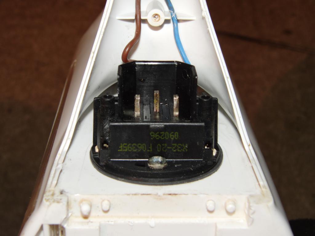 Power feed connector | 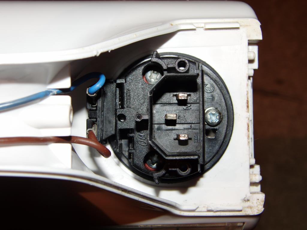 Power feed connector | 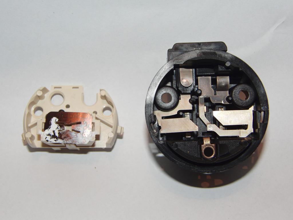 Power connector and thermal cutoff, bimetal strip visible | 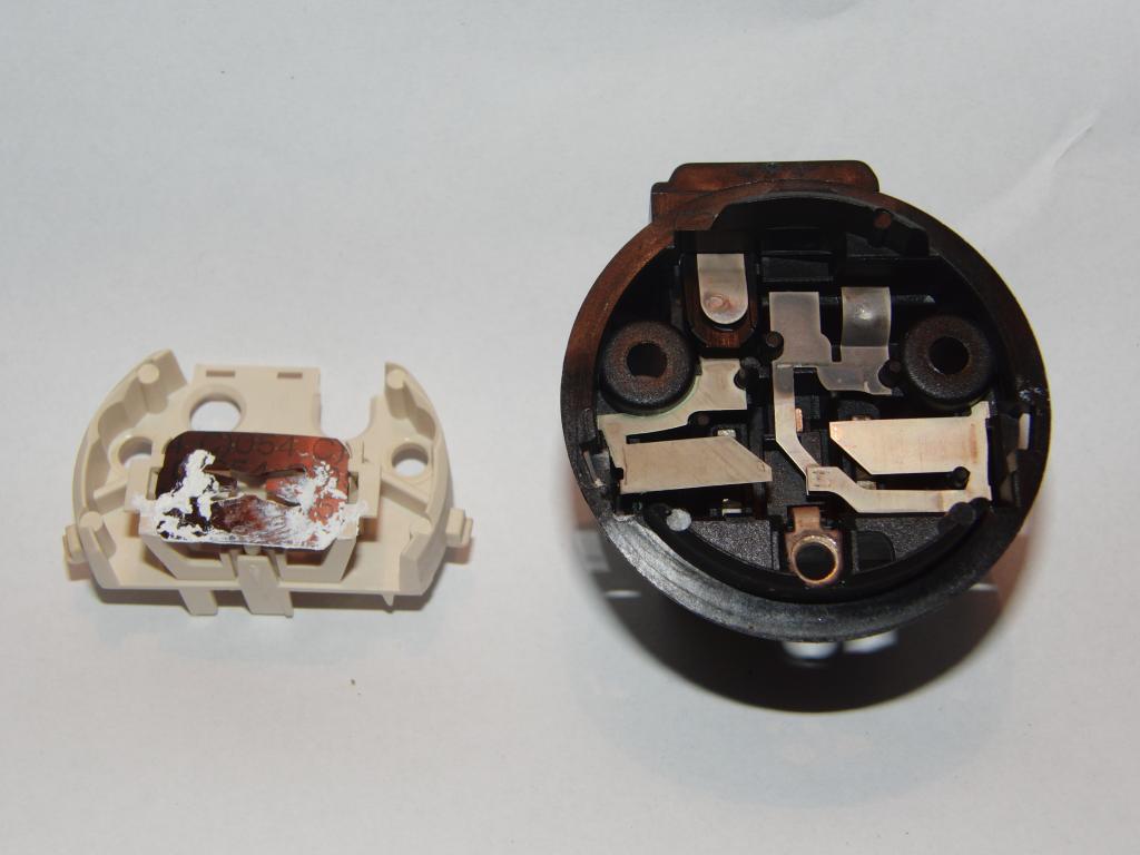 Power connector and thermal cutoff, bimetal strip visible |
 Power connector and thermal cutoff | 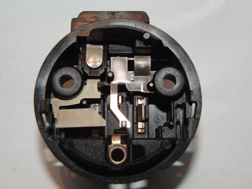 Power connector and thermal cutoff | 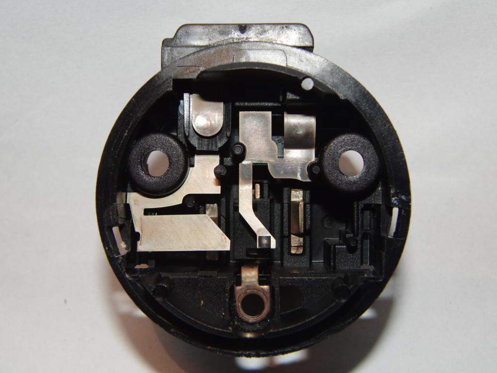 Power connector and thermal cutoff | 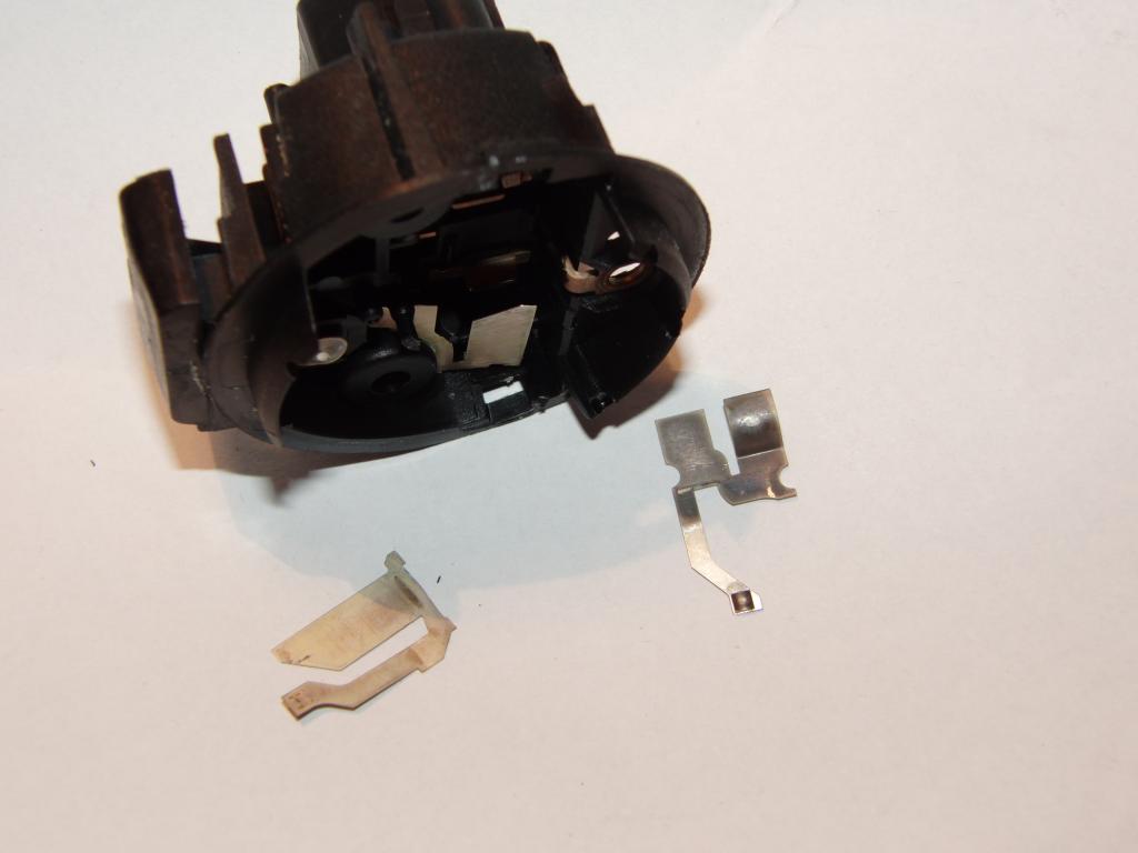 Power connector and thermal cutoff |
 Power connector and thermal cutoff | 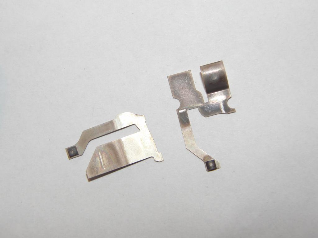 Power connector and thermal cutoff |
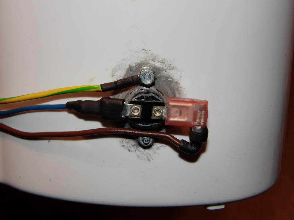
A hole was drilled to the side of the kettle, just a little above the heater. The thermostat module was mated into it and sealed with a rubber gasket (which also provided a distance separator for the thermostat holding element so the thermostat's sensing surface would be roughly flush with the kettle's inside surface). Silicone caulking was also added between the thermostat and the hole, to prevent water leaks. The thermostat body was held in place using the factory-supplied holding element from the outside and using a pair of larger-diameter washers from the inside. The screw heads and the washers were covered with a layer of hot-melt glue, as a protection against corrosion.
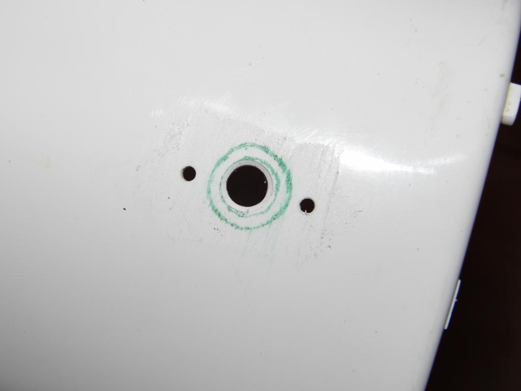 Thermostat hole | 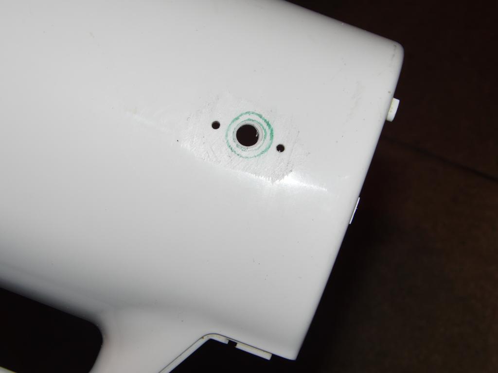 Thermostat hole | 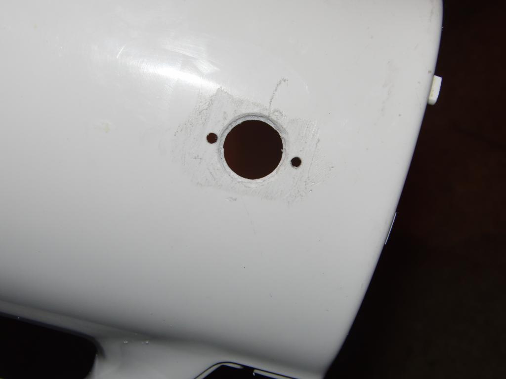 Thermostat hole | 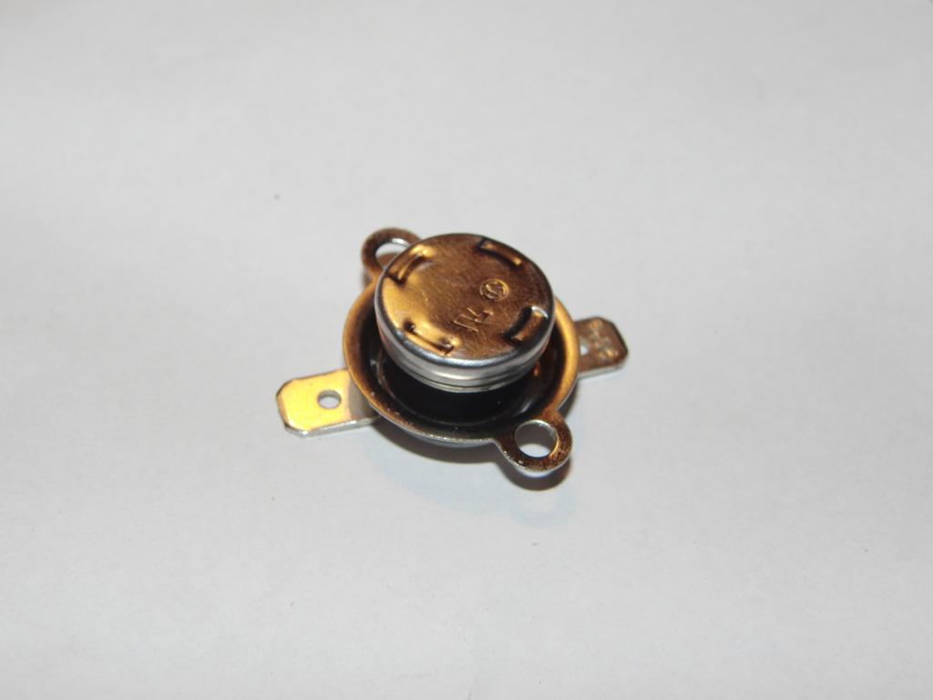 Thermostat |
 Thermostat | 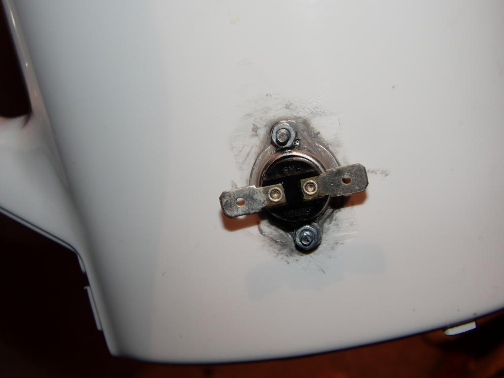 Thermostat in place | 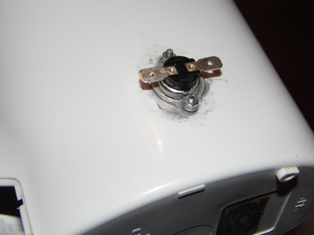 Thermostat in place | 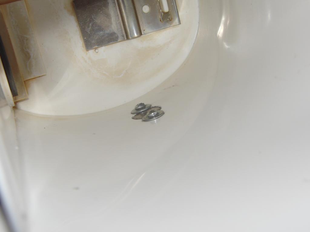 Thermostat in place |
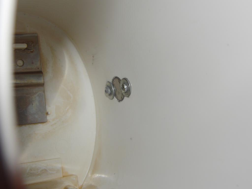 Thermostat in place | 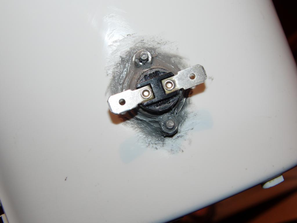 Thermostat in place, silicone caulking | 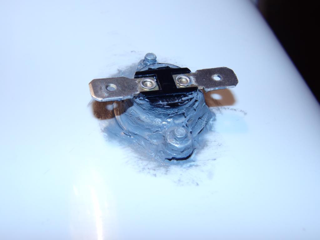 Thermostat in place, silicone caulking | 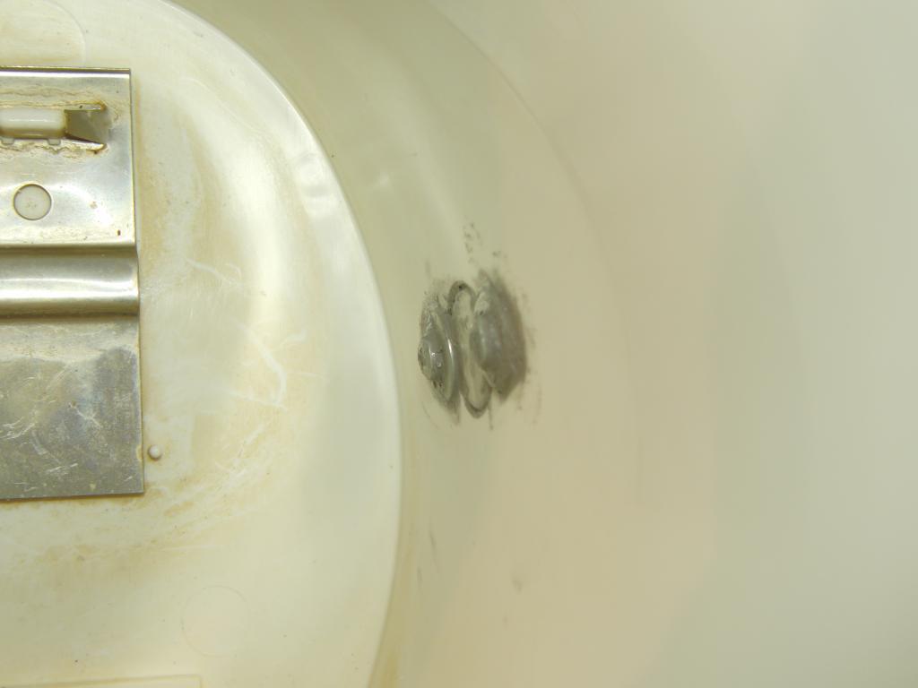 Thermostat in place, silicone caulking |
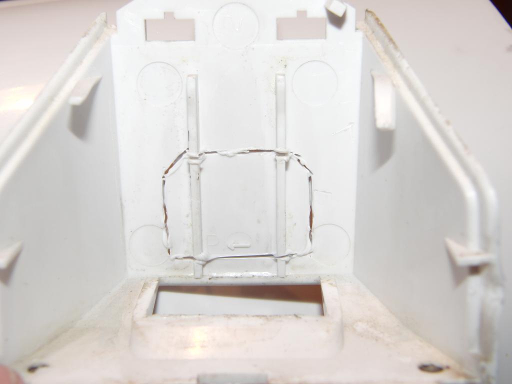
A standard IEC power socket was chosen as an alternative to a power cord or a stand-on base. A mounting hole was cut out to the plastic part on the base of the unit and a snap-in socket was inserted and secured with hot-melt glue.
 Power socket mount | 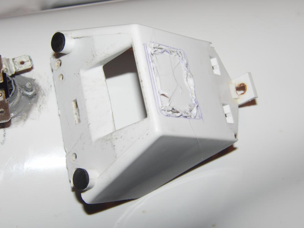 Power socket mount |
For an initial test the power socket was directly wired to the heater and the thermostat.
 Thermostat wiring | 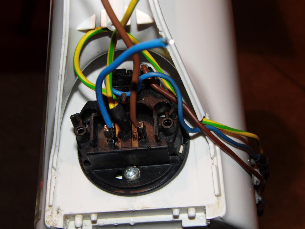 Power wiring | 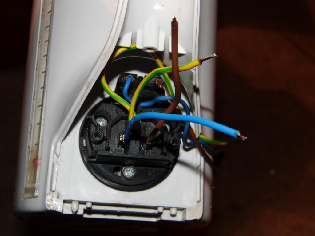 Power wiring | 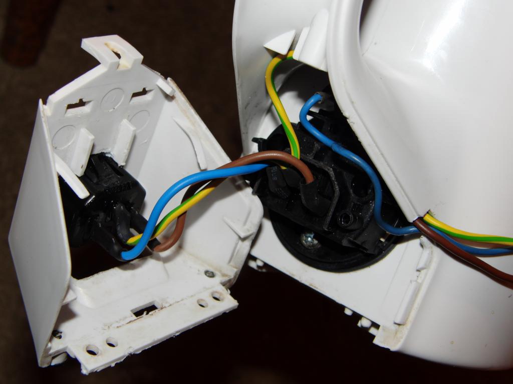 Power wiring |
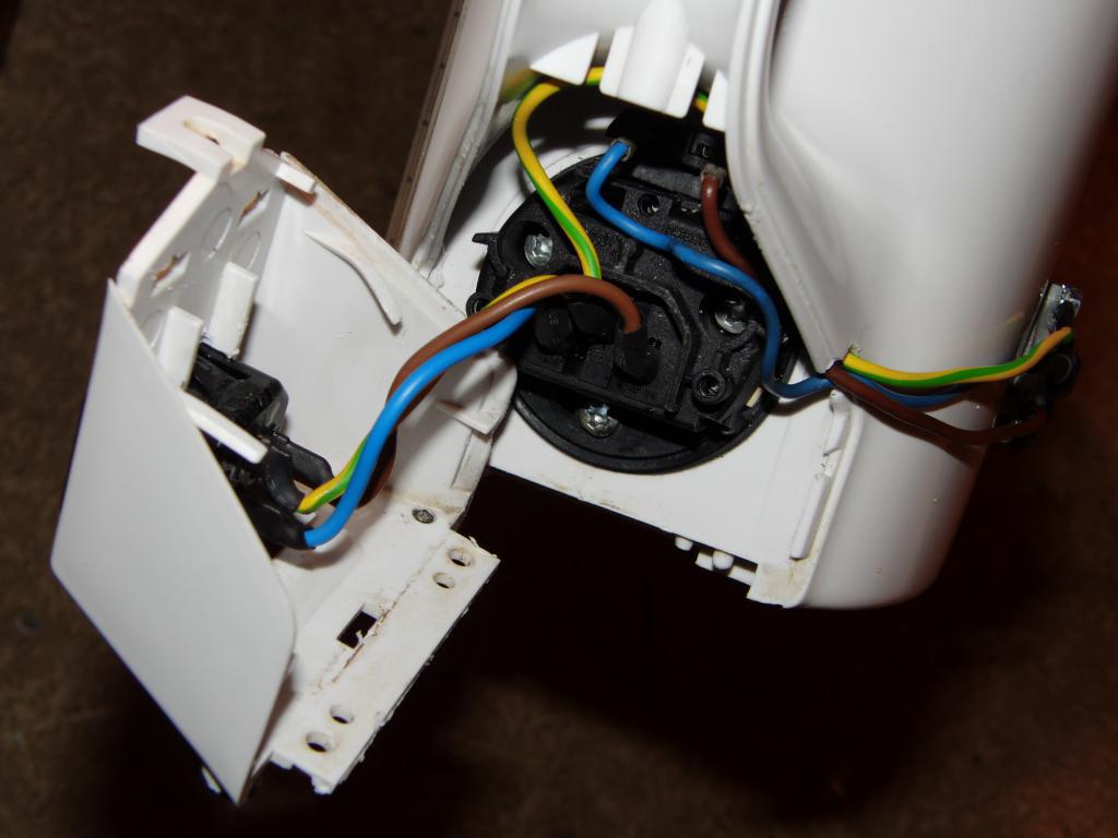 Power wiring | 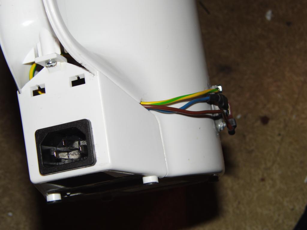 Power wiring |
The kettle was filled with water. And found to be leaking.
The thermostat held fast and tight. The suspicion fell to the heater gasket. The assembly was unmounted and the gasket smeared on all sides with silicone caulk.
The test was repeated when the silicone cured. And the leak persisted.
The leak was found to be at the bottom of the sight glass. The tube was removed and silicone caulking applied to the seals.
Subsequent tests were leak-negative.
 Sight glass removed | 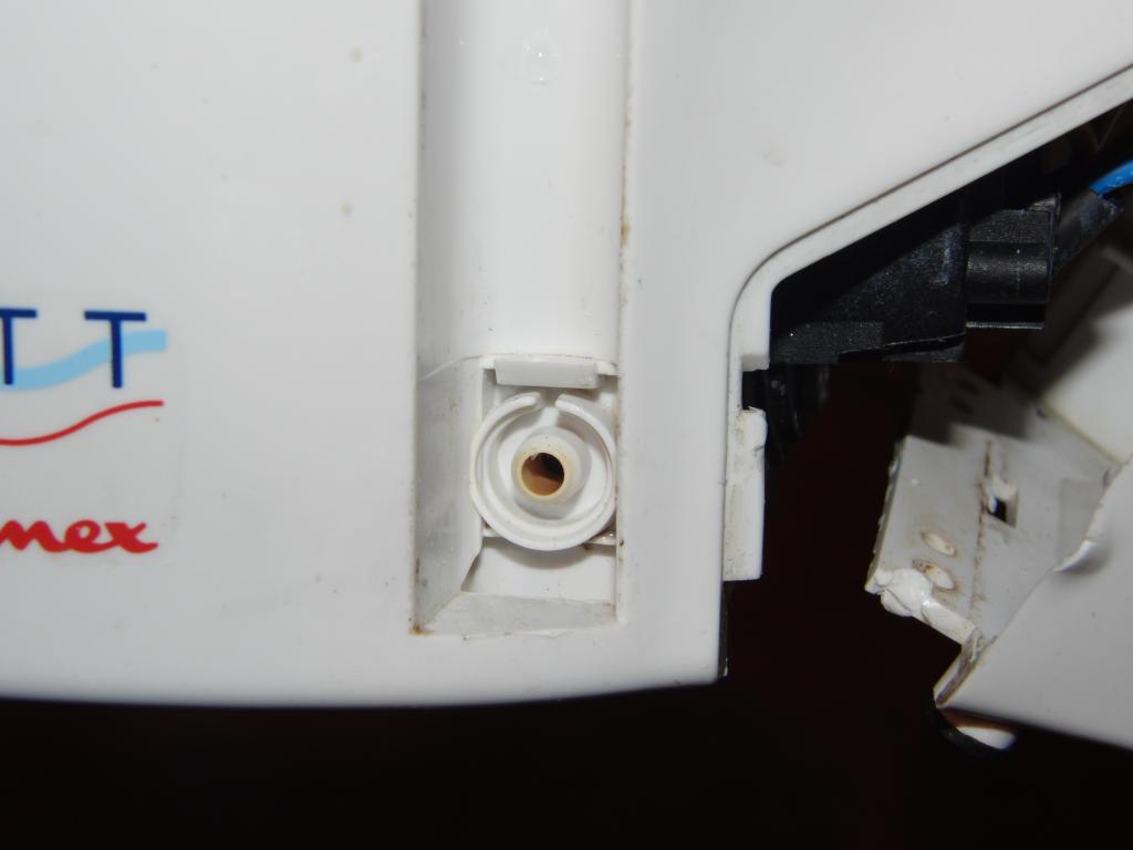 Sight glass removed | 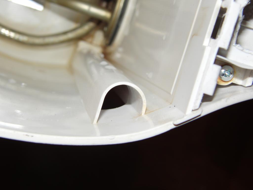 Sight glass removed | 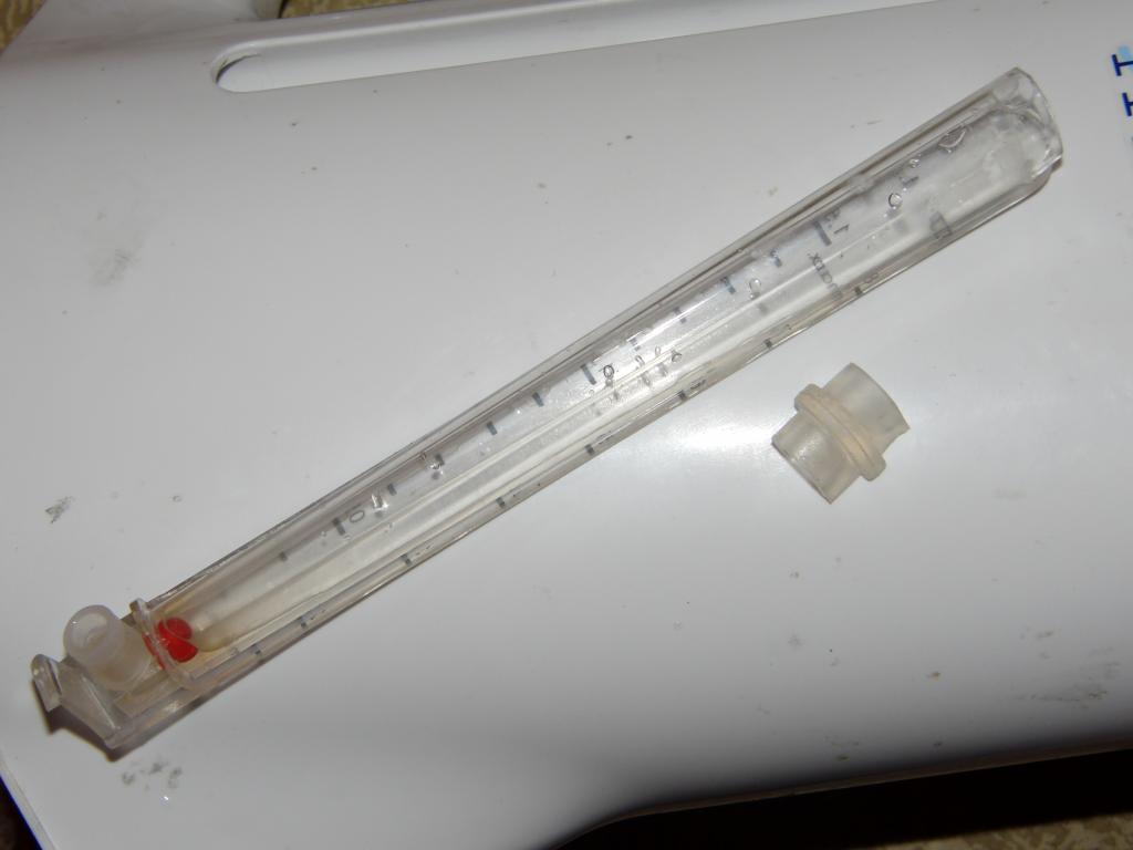 Sight glass removed |
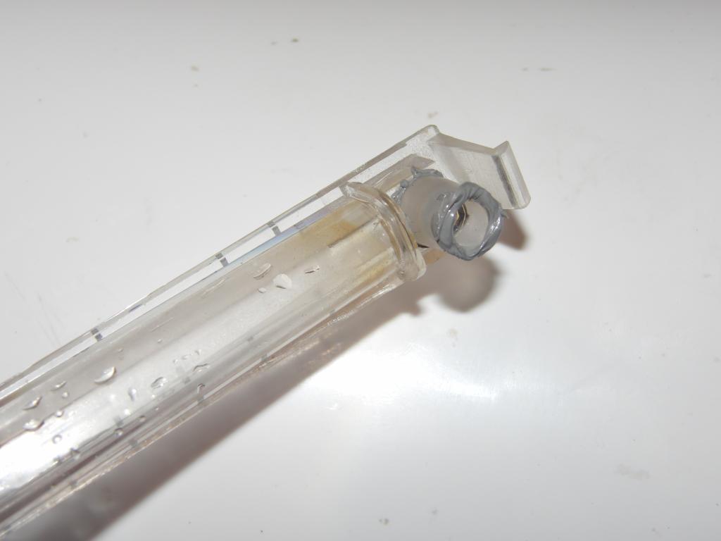 Sight glass with silicone caulk | 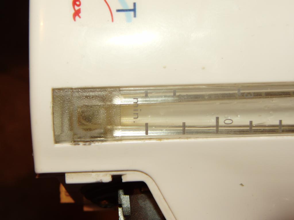 Sight glass with silicone caulk | 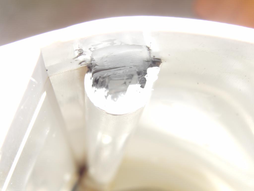 Sight glass with silicone caulk |
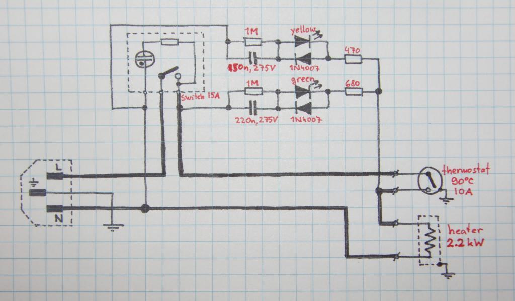
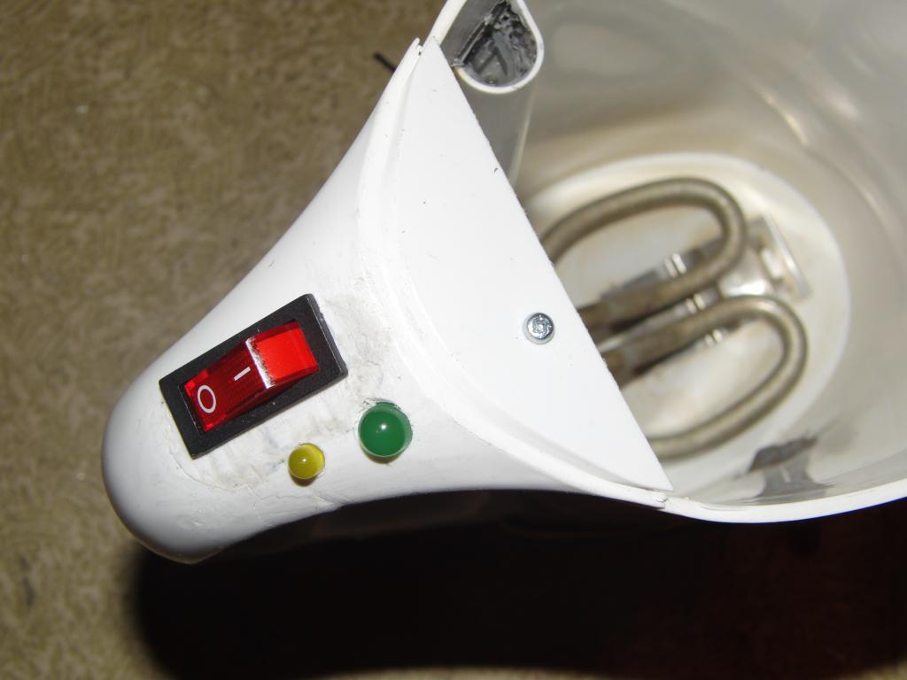
The hot water bath Mk.1 control panel is about as simple as it can be; only a main switch and a pair of LEDs, a 5mm yellow one indicating that the heater runs and a 8mm green one indicating target temperature reached.
The LEDs are powered directly from mains, and the voltage on them is brought down using a serial capacitor (using reactance instead of resistance, for avoiding the thermal losses) and a resistor (to reduce the magnitude of power-on current surges through the LED). The high-value resistor parallel to the capacitor serves to safely discharge it on power-off, to prevent unpleasant surprises during disassembly; the stored energy for 320 V (peak AC value) and 220 nF is only about 11 millijoules, so it is safe, but it is not pleasant anyway). The series capacitors should be ideally the Y2 type (guaranteed to fail open instead of failing short), but smaller cheaper non-Y2 (most often the X2 type will be employed) can be used as in this position in the schematics the short-fail will in worst case trip the breakers, but is more likely to burn the series resistor and make it act as a fuse, or blow the LED, or both.
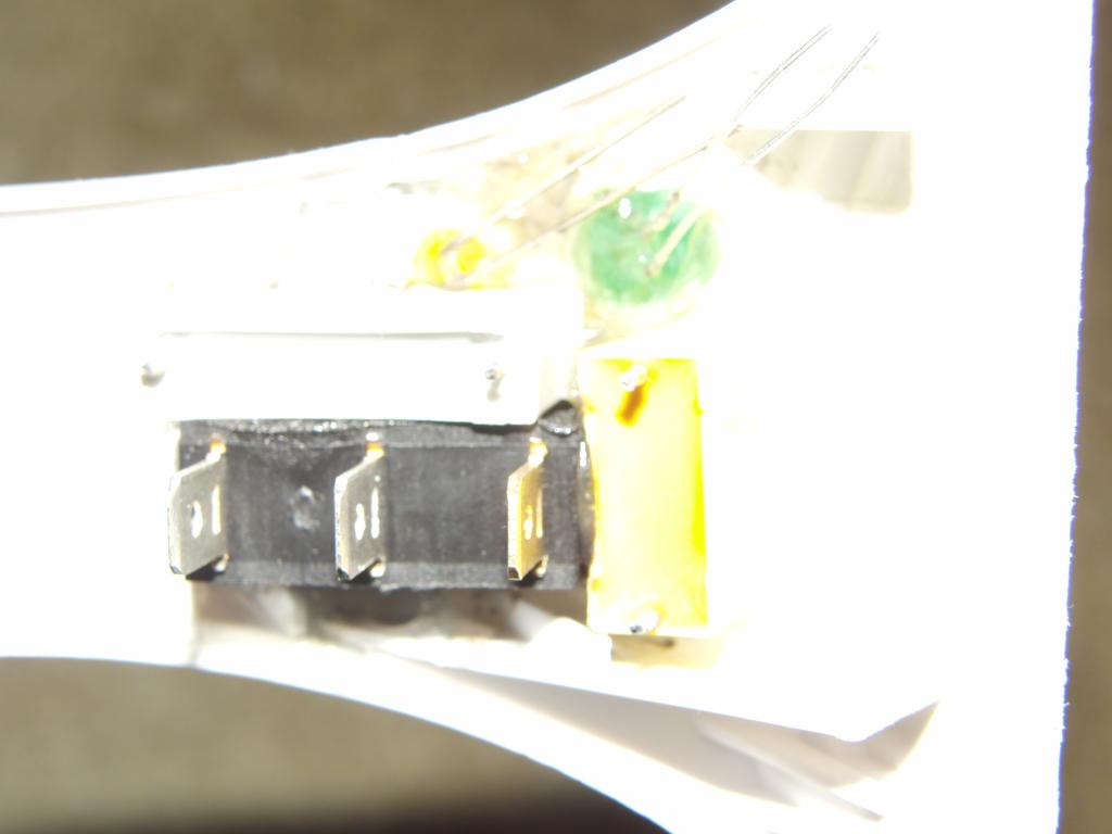 Power switch and LEDs | 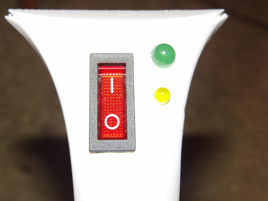 Power switch and LEDs | 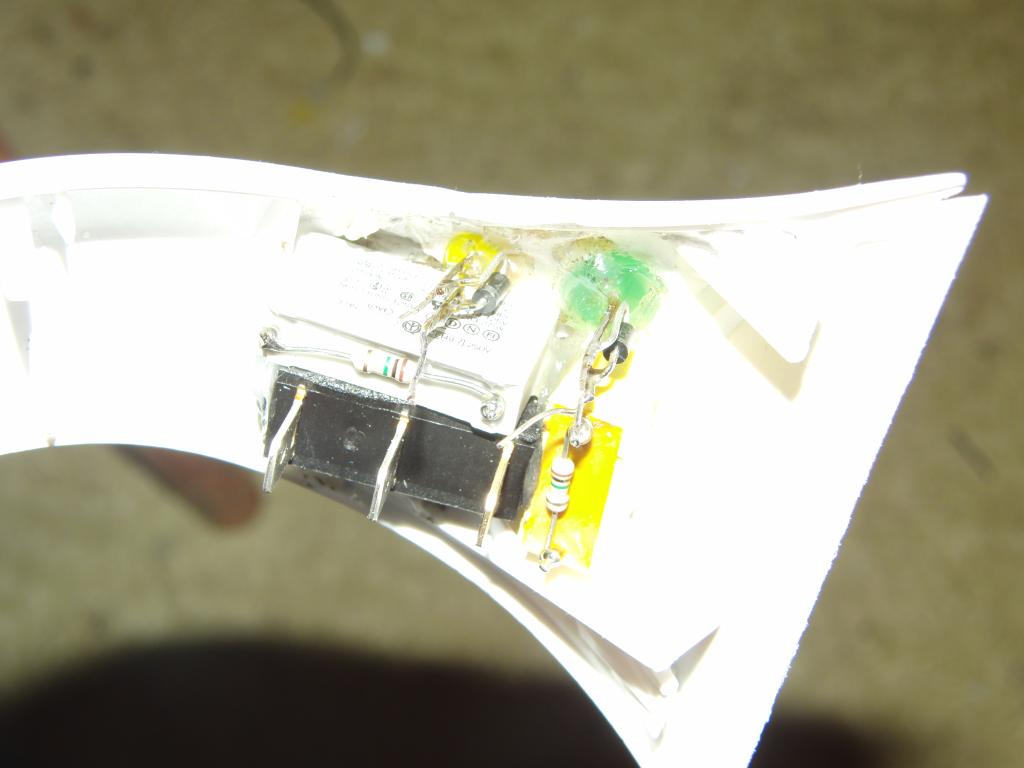 Power switch and LEDs | 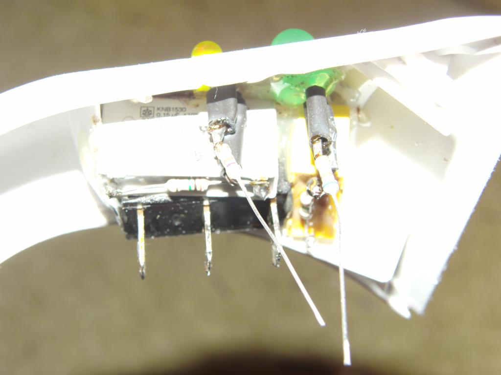 Power switch and LEDs |
 Control unit | 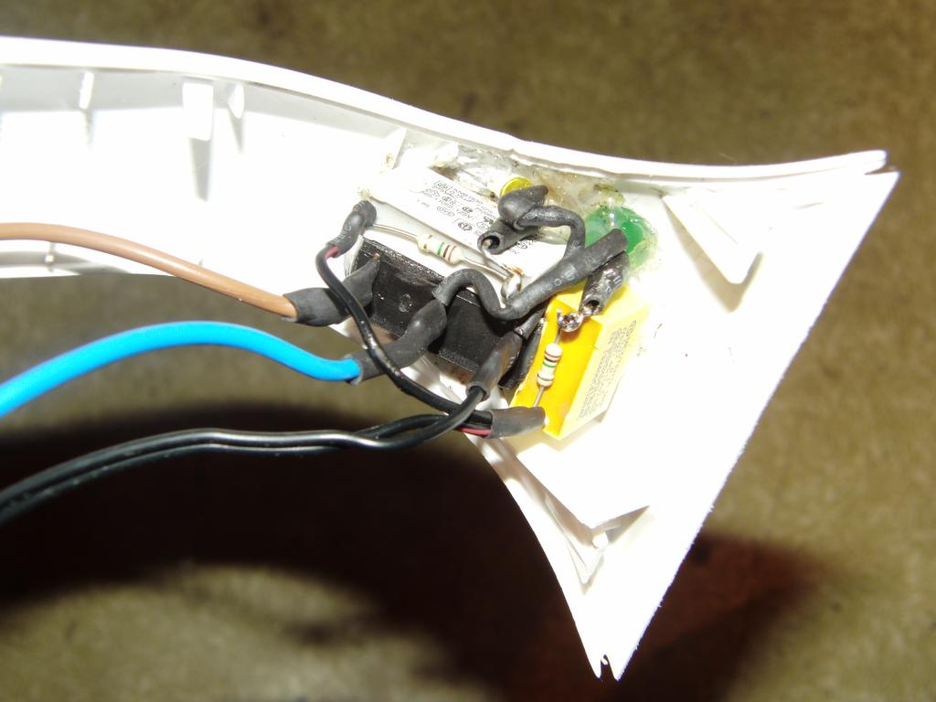 Control unit | 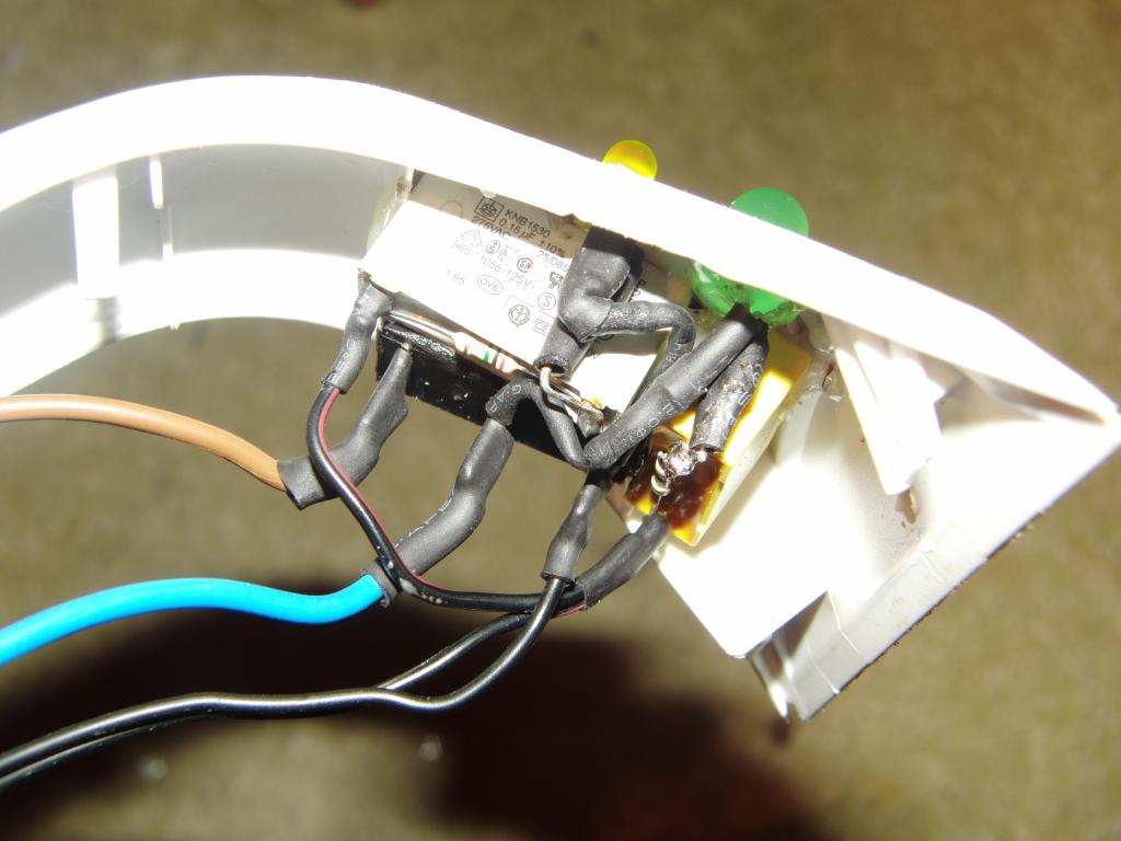 Control unit | 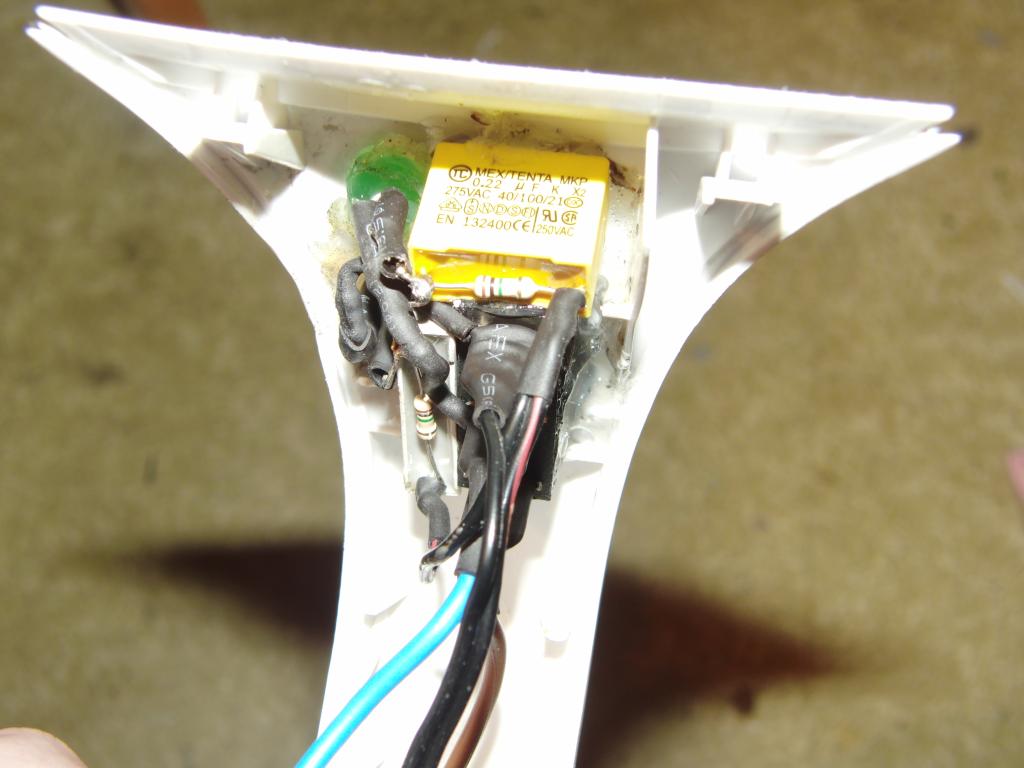 Control unit |
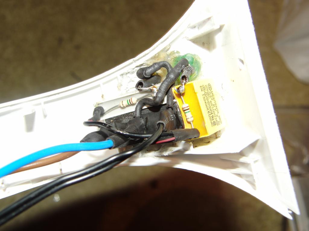 Control unit |
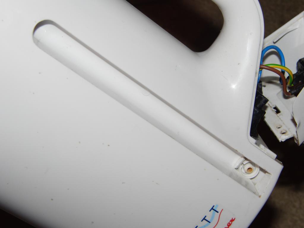
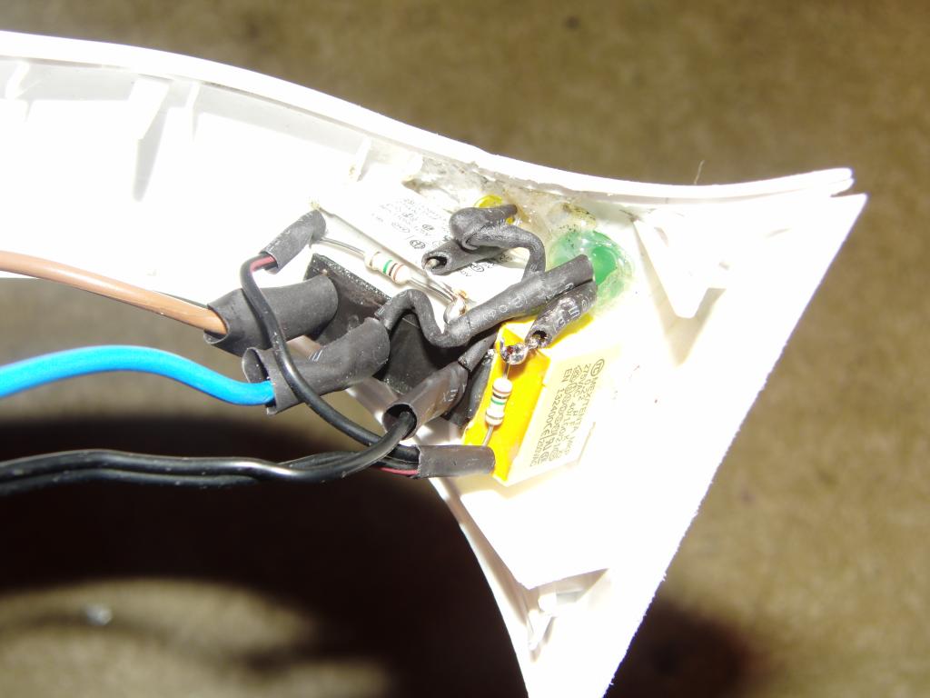
The wiring between the power socket, switch, indicators and heater is mostly concealed in the kettle's handle. The wires for the thermostat are led over the kettle surface.
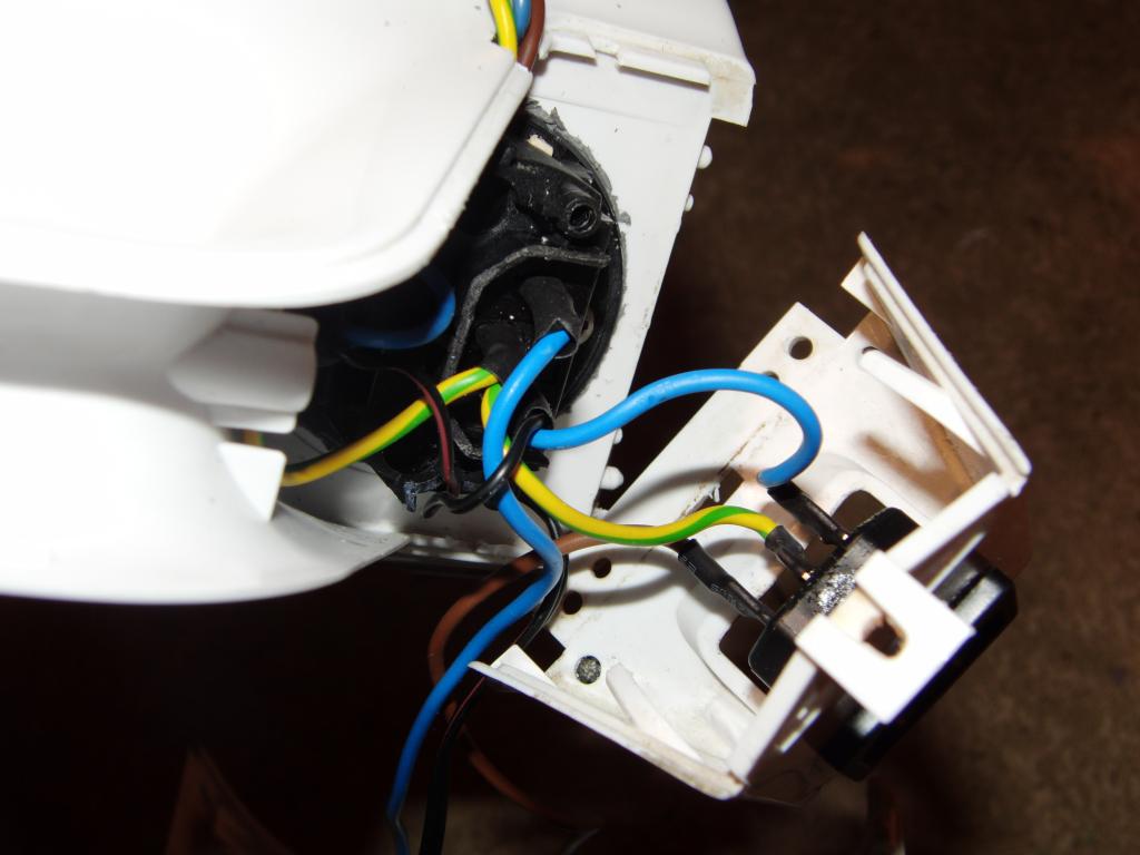 Power and control wiring | 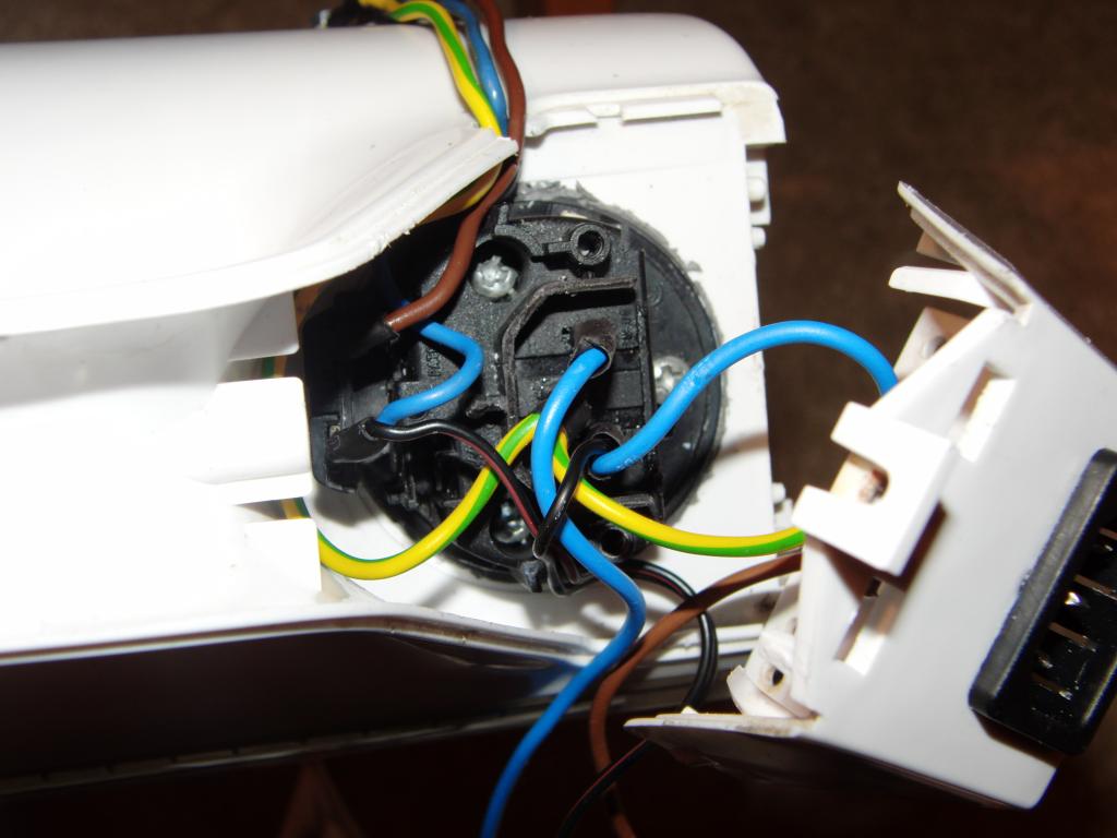 Power and control wiring | 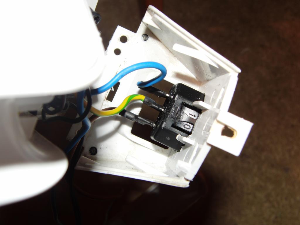 Power and control wiring | 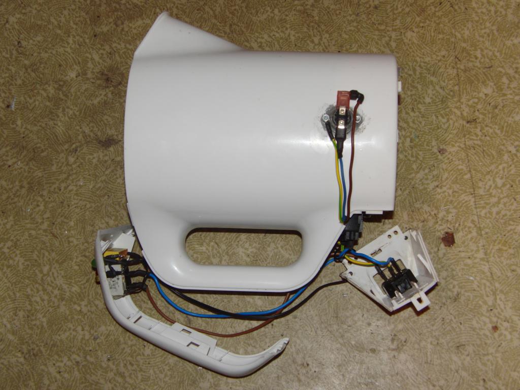 Complete wiring |
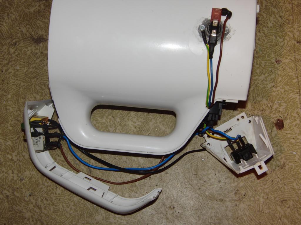 Complete wiring | 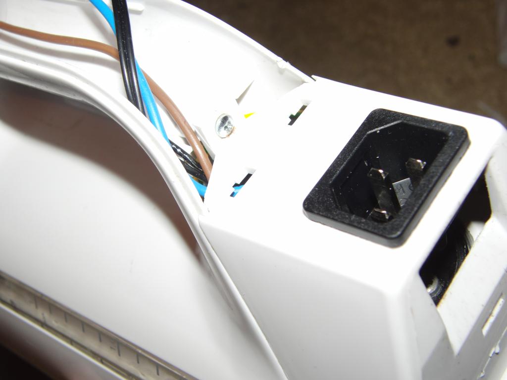 Power socket |
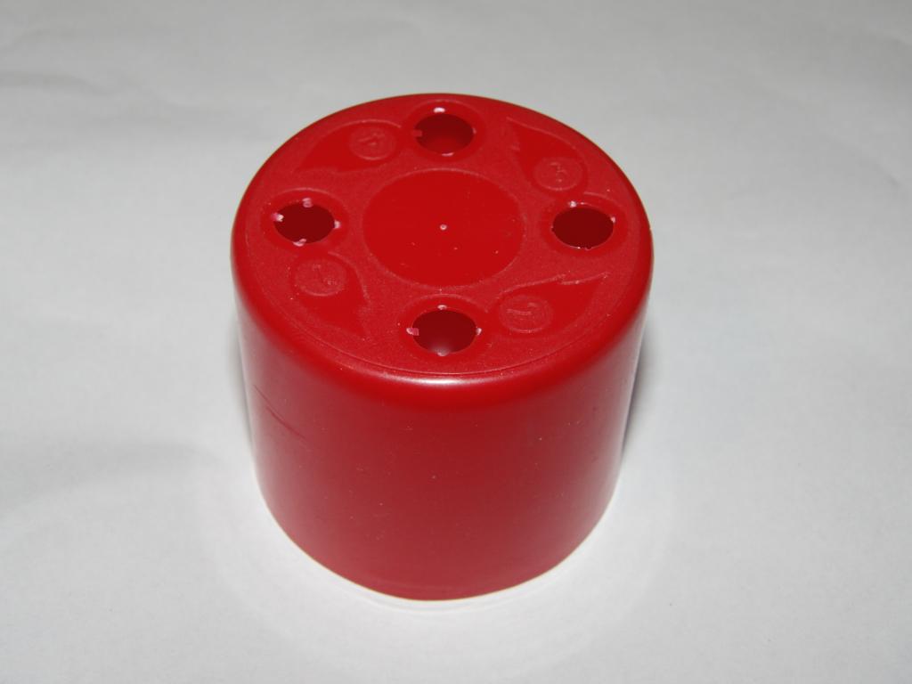
The cover for the thermostat was made from a cap from a lighter butane "spray" can. The cap was cut off to the desired height, then the cut profile was tweaked to fit the curvature of the kettle side. The holes, in which the various lighter adapters were seated, were filled with a red art-type hot-melt glue that fairly well matched the color. Two holes for M3 screws were drilled in and a cutout for the wires was made on the side.
A pair of male-female M3 standoffs was mounted onto the protruding ends of the screws holding the thermostat, effectively prolonging them. Their male ends were stuck through the holes in the cap and the cap was secured in place with a pair of acorn nuts. (A female standoff, a tall nut, was originally intended to be used, but it turned out to not be easily available - there was only one in the box of nuts. Apparently the others were eaten by a squirrel.)
 Thermostat cover, butane gas cap | 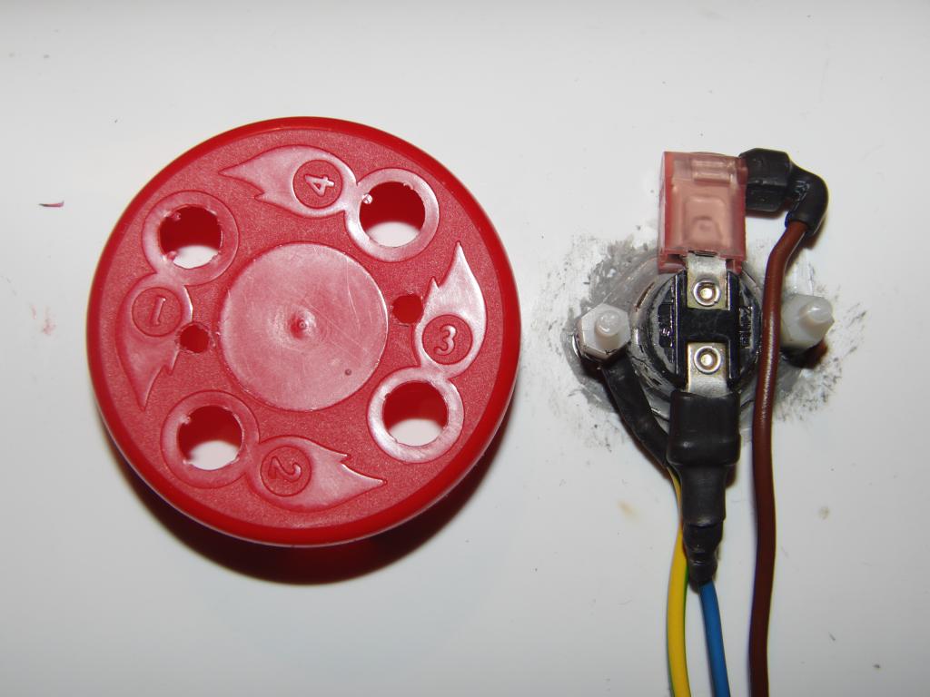 Thermostat cover, cap cut off | 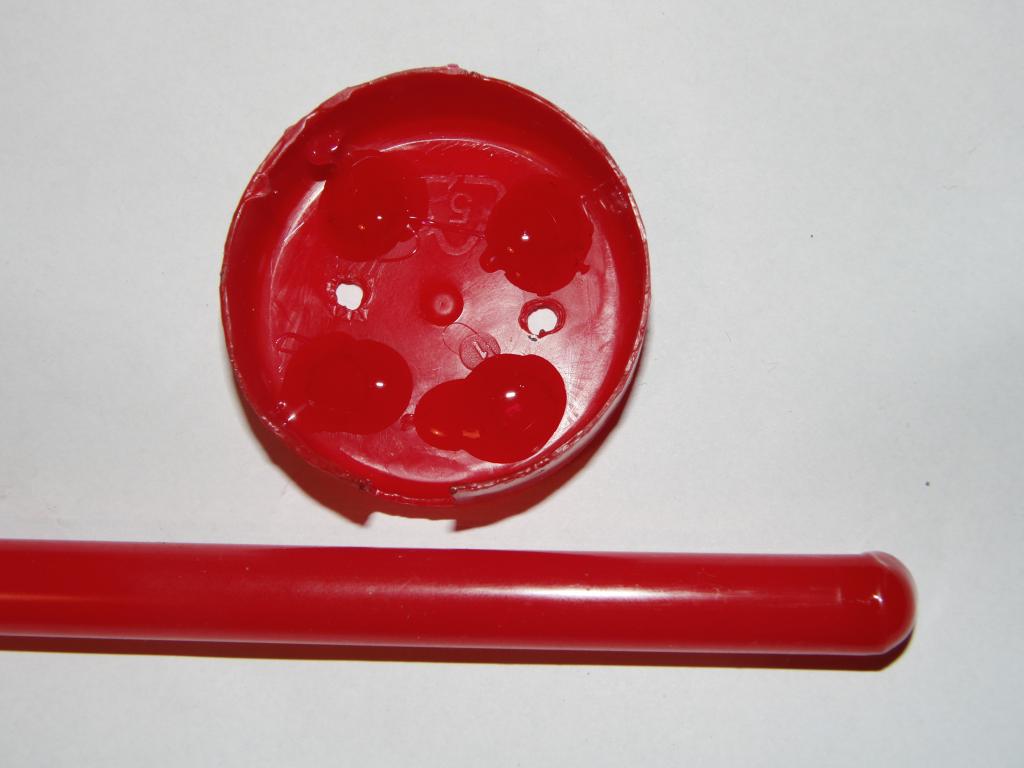 Thermostat cover cap with holes sealed with colored hot-melt glue | 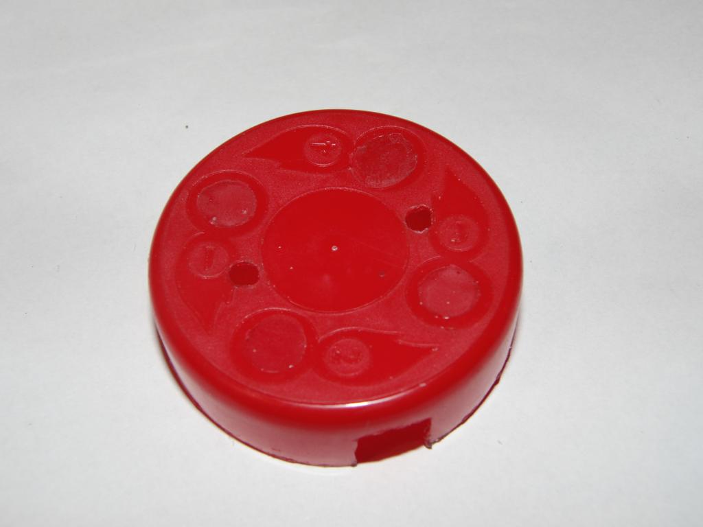 Thermostat cover cap with holes sealed with colored hot-melt glue |
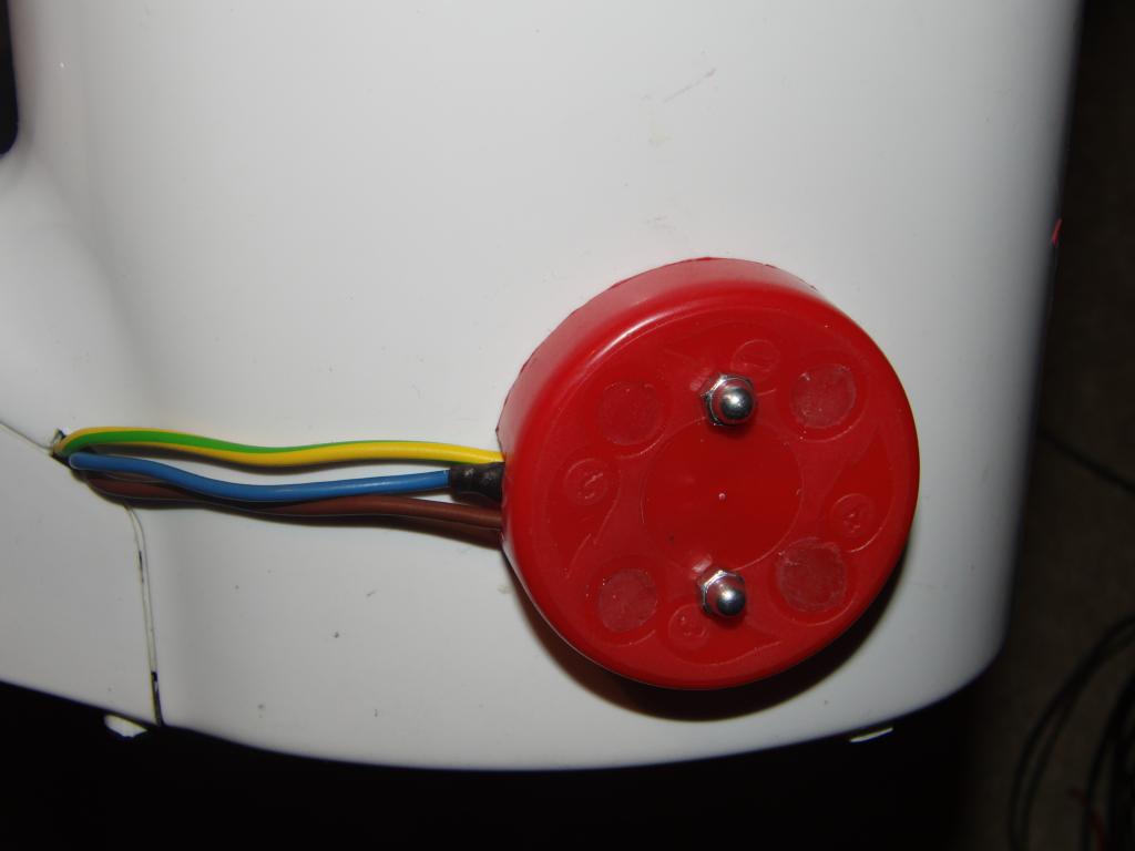 Thermostat cover cap in place |
The resulting device appears to be working fairly well. Due to the high heater power (about 2kW) the heating up is fairly rapid. Once the thermostat switches off, it stays off for a significant time (the bath cools slowly) and the heating periods are relatively short. The heat transfer between the water and the thermostat is somewhat delayed; the first heat-up gets the water almost into boil before it gets switched off, the subsequent ones (when the thermostat is already heated through) are not overshooting so much.
 Top with switch | 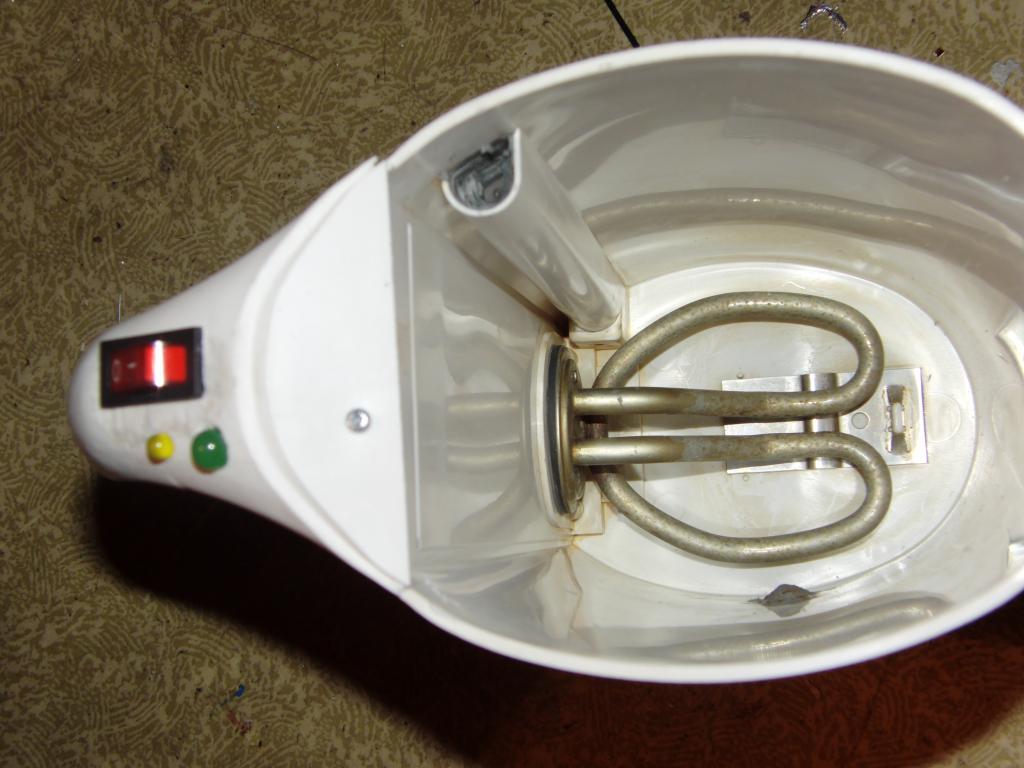 switch and heater | 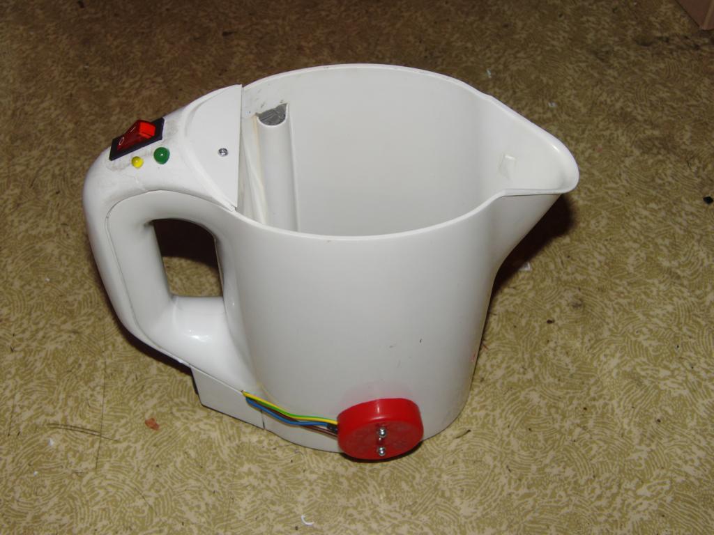 Finished unit | 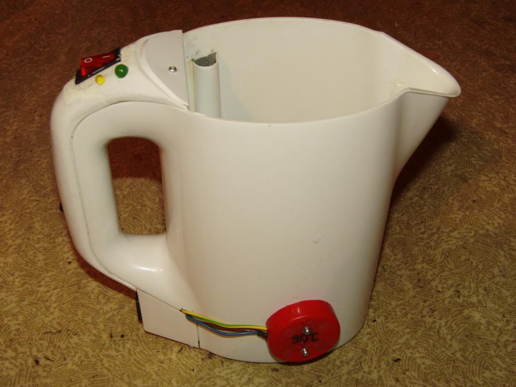 Finished unit |
 Finished unit |