Because I needed to switch a bank of five monitors (three flat-panels, two CRTs) from one switch. I originally used a 12-volt relay, but that turned out to be suboptimal; the inrush current for all five power supplies was so high the relay contacts tended to get welded together and occassionally required a swift tap to disconnect, gradually degrading until they had to be replaced. As solid-state devices tend to have much higher peak current capabilities, after wasting the third relay I decided to replace the whole design.
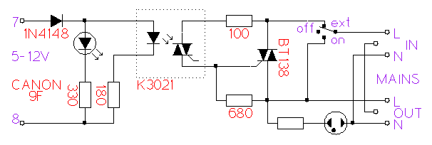
The unit is just a simple triac switch using a BT138 triac, with an optoisolator calculated to handle 5 to 12 volts. Future upgrade to USB control is thus possible without modification of parts values.
The unit lacks a snubber . This was omitted due to the capacitive nature of the load. Transients on the mains may open the triac
momentarily. The unit is however connected through a transient suppressor, and problems of this nature were not observed so far,
except for moments when the power is switched on after a blackout and the coupled capacitance causes a transient that momentarily
opens the triac.
. This was omitted due to the capacitive nature of the load. Transients on the mains may open the triac
momentarily. The unit is however connected through a transient suppressor, and problems of this nature were not observed so far,
except for moments when the power is switched on after a blackout and the coupled capacitance causes a transient that momentarily
opens the triac.
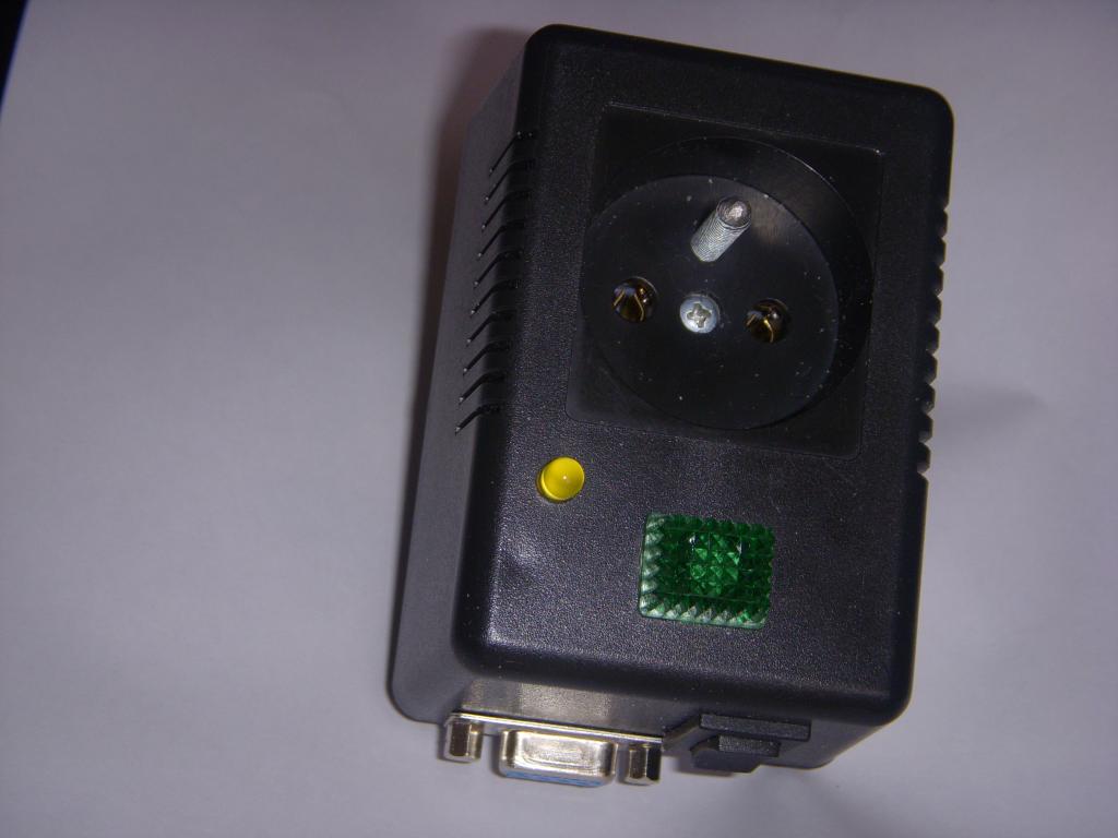 Outside view, top | 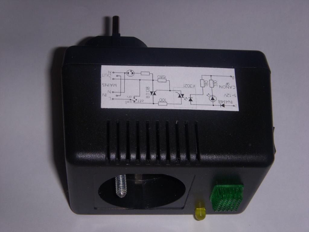 Outside view, side | 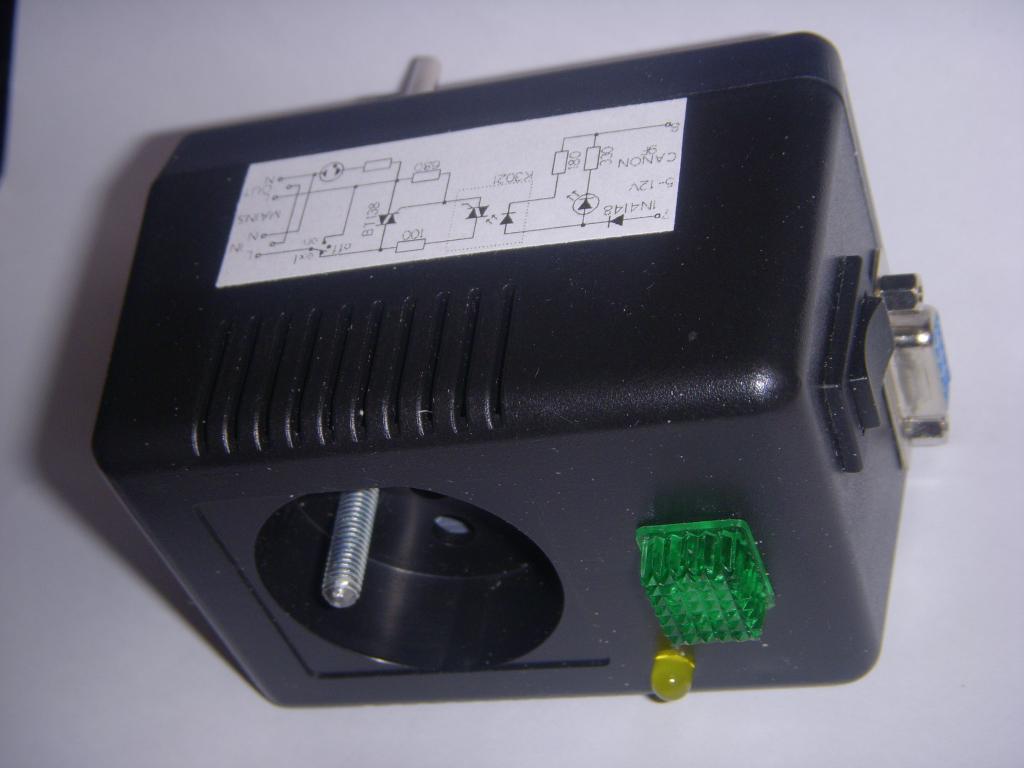 Outside view, top-side |
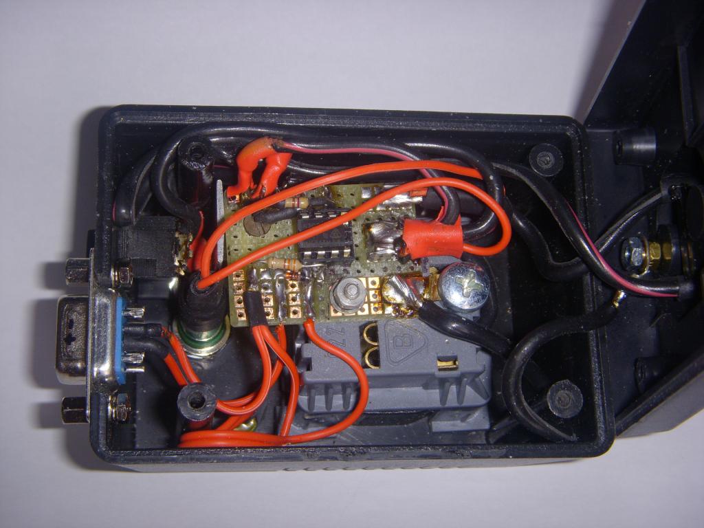 Inside view | 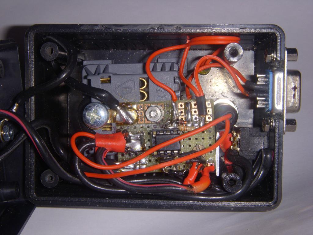 Inside view | 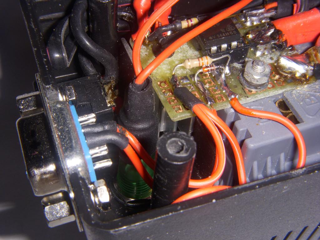 Low-voltage part, detail |