Remote RESET is a cable adaptor that permits one PC with RS232 to reset another by shorting the RESET jumper on it's motherboard. Should be usable to switch other signals as well (eg. Power button, etc).
In a warehouse in a kingdom far far away, there was a computer. The computer was performing an otherwise unimportant important function. But an evil fairy cursed the poor machine to run Windows-based software, causing it to hang every while. Something had to be done. Fast.
So a remote reset device was born.
There was a computer nearby, running Windows 2000, and a reliable server on the LAN. The only thing that wasn't there was time. So the solution had to be simple and made from immediately available parts.
The original idea was to use a reed relay in parallel to the reset switch, controlled from a RTS or DTR signal from the RS232 (COM) port of the computer nearby. But then I realized that there is a problem with Plug'n'Play device autodetection in Windows, during boot, when Windows look for mice and modems and other devices. During this process, the RTS and DTR signals are put to 1, then to 0, in a sequence (as shown here and here). This would cause the supervised computer to reset while the supervising computer boots up. Which we don't want it to do.
We start with DTR=0 and RTS=0. The PnP detection sequence first puts DTR to 1, then in next phase raises RTS to 1 as well, then drops them both to zero. So the RTS=1,DTR=0 combination is free. So we put the signal as the difference between those two.
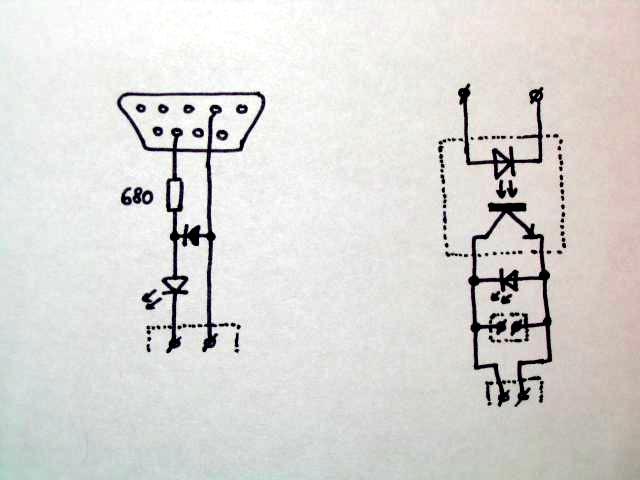
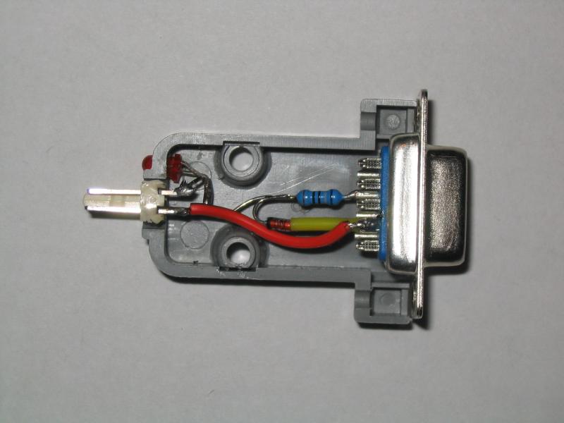
We experimentally found that we don't have to use a relay; a spare optron did its job as well. We take a LED and connect it in series to the optron, so we can indicate its operation. In parallel with them, we put an inversely polarized diode, in order to protect the sensitive LEDs from the high reverse voltage of the RS232 port, which could run up to 24 volts of difference. There is also a serial resistor connected to the LEDs, to limit the current through them; in this version it is 680 ohms, which is awfully low (the voltage difference can be as high as 24 volts) and should've been chosen higher as the overcurrent can dramatically shorten the lifespan of both the optron and the LED. However, given the duty cycle of the device (one second per blue moon), this shouldn't be an immediate concern; just remember it for the next version.
On the side of the other computer, we put the actual optron. To its controlled side we place a LED in parallel, in the reverse direction, so wrong polarization of the reset plug lights up the LED (and causes the computer to stay stuck in RESET state) and serves as an indication that something is wrong.
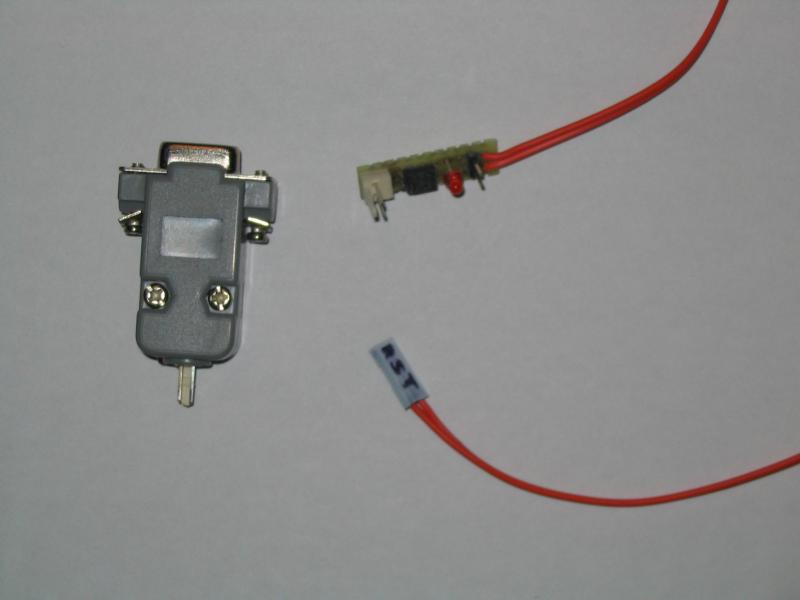
We built one part of the circuit inside the Canon9 connector case, with a small 2-pin connector as output. The LED goes through a hole drilled in the case.
The other part is to be hidden in the case of the supervised computer. The board has a connector on one side, for the controlling line, to which the LED from the optron is connected, and a 2-pin connector on the other side (to which the RESET button from the case is connected in parallel to the optron), and a piece of 2-wire cable, with a connector on the other end, to be connected into the motherboard's RESET SWITCH signal. The polarity here is critical. To detect the situation when it is wrong, there is a LED in parallel to the optron.
For the trigger itself we need anything that will allow us set/clear the DTR and RTS signals on the port. For Windows RealTerm will do, for Linux a custom program is needed (under construction).
We use a script that periodically queries a service running on the supervised computer from the supervising
one. If the service isn't accessible for several consecutive times, a RESET signal is issued (the RTS pin
on the supervising computer is set to 1, DTR to 0, for one second, then both are set to 0 again).
For this purpose, RealTerm is employed. When there is
the time to reset the controlled machine, we invoke the command
realterm PORT=1 RTS=1 DTR=0 VISIBLE=0 CAPFILE=x.txt CAPTURE=1 CAPSECS=1
(run on port COM1, set the signals for 1 second, be minimized in tray).
Resistor 1 kΩ (or 2.2 or so), for the LED and optron current limiting
Diode, any small type (eg. 1N4140), for protection of the LED.
Optron, any suitable[1]. PC817 was used in the prototype.
LED, 2 pieces, any suitable.
Connector Canon 9pin female, for the RS232 port. Casing optional but suggested.
Suitable connectors for cables and jumpers.
[1] Has to have sufficiently small resistance in open state. The crucial values likely depend on the motherboard being controlled. If your motherboard will ignore you (unlikely, it worked on several machines, but one never knows) check with an ohmmeter if the switching works. If yes, and the board still ignores you, try a different optron. There is also the possibility of replacing the optron with a reed relay, with its coil directly connected to the COM port; a typical 12V reed relay has a 1000 ohm coil, which is within the range the serial ports could be able to drive.
 both ends of the unit | 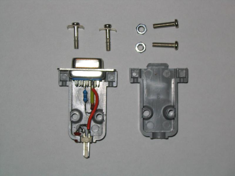 COM end, parts | 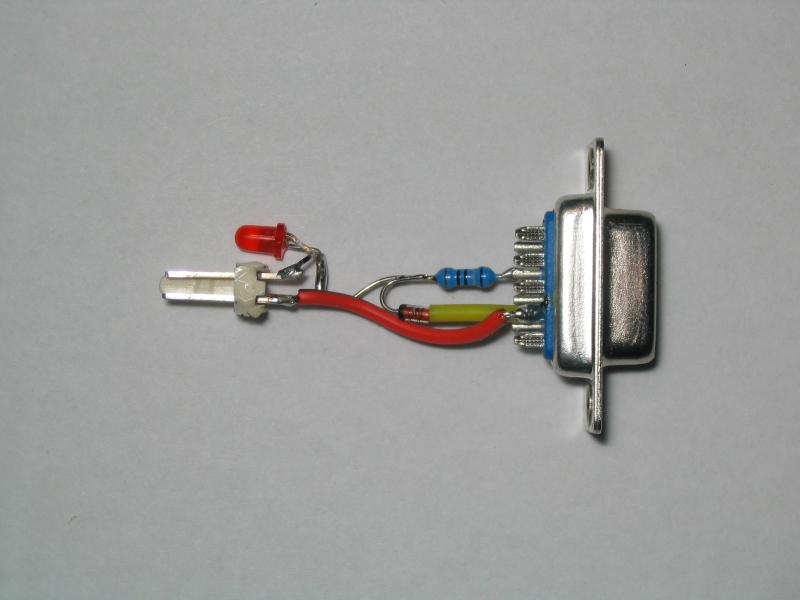 COM end, electronics | 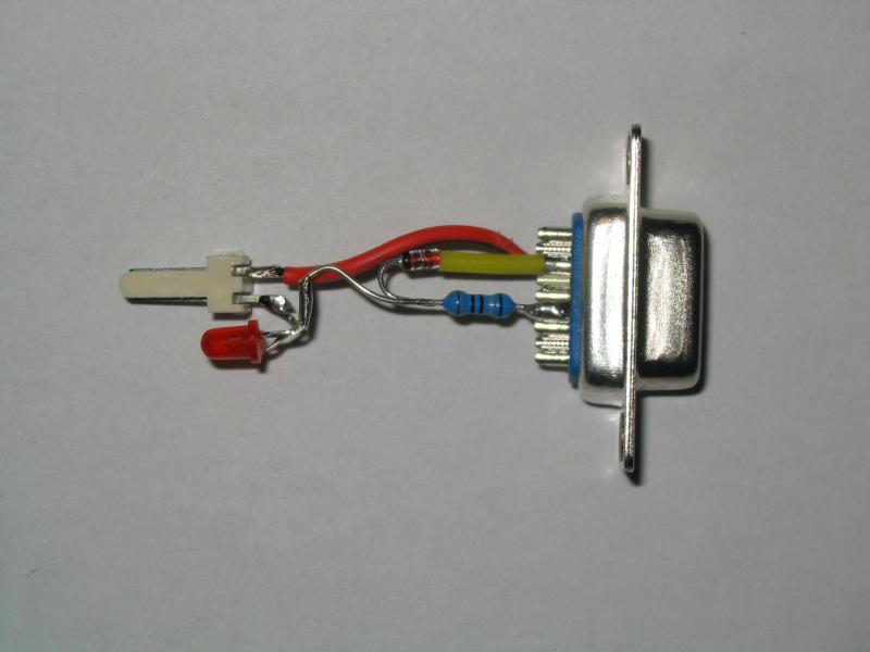 COM end, electronics |
 COM end, detail | 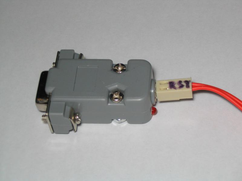 COM end, connected | 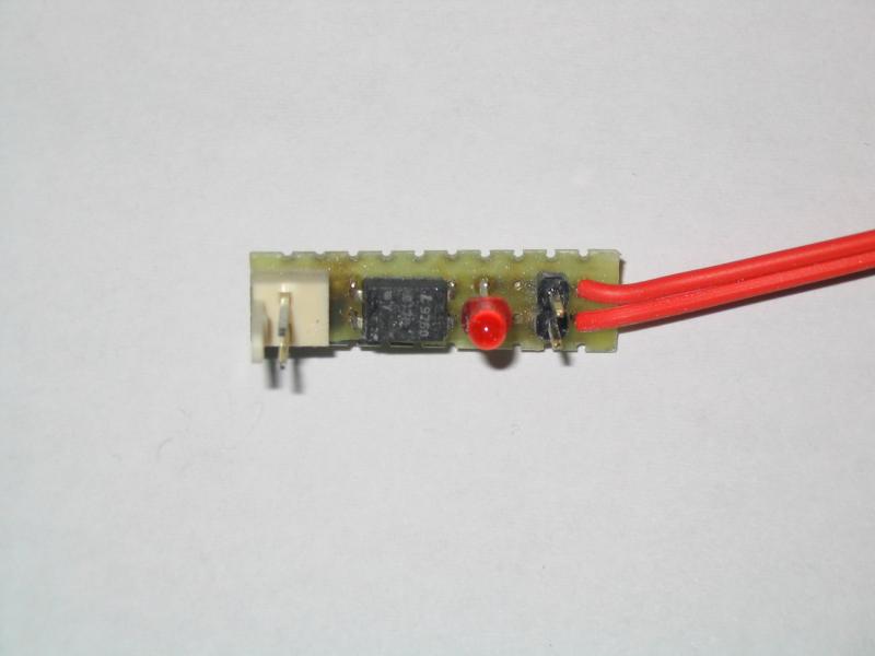 RST end, detail | 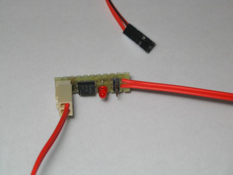 RST end, connected |