 . The method is very versatile,
allowing all sorts of programming of 2D and 3D parts. 2D contours suitable for laser cutting can be
exported as DXF format. The dimensions are in millimeters.
. The method is very versatile,
allowing all sorts of programming of 2D and 3D parts. 2D contours suitable for laser cutting can be
exported as DXF format. The dimensions are in millimeters.
The market is full of cheap, 40-watt CO2 lasers. Typically they are derived from the K40 type, a cheap Chinese one. They usually use MoshiDraw, a quite atrocious but somewhat functional control software for cutting and engraving.
Parts for cutting can be easily drawin in parametric way using OpenSCAD. The method is very versatile,
allowing all sorts of programming of 2D and 3D parts. 2D contours suitable for laser cutting can be
exported as DXF format. The dimensions are in millimeters.
MoshiDraw imports simple DXF files fairly well.
OpenSCAD produces a very simple, rudimentary form of DXF. The only entities present there are LINE. Circles and round parts are drawn as polygons. The number of facets can be controlled via variables $fa, $fs, and $fn (see the language documentation).
MoshiDraw rearranges the order of objects to draw in a somewhat opaque fashion. This can and does result in erratic laser head movements, where parts are drawn out of order.
Experiment proved that MoshiDraw supports the DXF LWPOLYLINE entity, and that such entity is honored in drawing the line; all its parts are drawn together in the proper sequence.
Another problem is generation of files for e.g. panelization, or for sequential cutting and engraving of the same parts. Shifting, scaling, and mirroring operations are needed, preferably from a script.
Of course, no simple non-bloatware DXF handling tools were available.
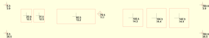 DXF file of a back panel of an instrument, displayed without the outline; inner cutouts have cross-marked centers and their coordinates are shown. Command: dxf2png.sh -bgcol lightyellow -lcol red -cro -cm -cfs 80 x.dxf -o dxf2.png |
Several simple programs were written in C. C language was chosen for its availability; Python or Perl would do the job as well.
The utilities support only the LINE and LWPOLYLINE entities. LINE is the only one used by OpenSCAD, LWPOLYLINE is output of the utility. No others are needed anyway. Support for more may or may not be added in the future.
For some odd reason, the output of this code works well only with MoshiDraw 2013. On version 2014 it refuses to read the files as it is not the DXF(R11) version. (To accept lwpolylines, $ACADVER has to be set to AC1015 for the MoshiDraw 2013 version, on which 2014 version fails with the version complaint. AC1011, AC1012 and AC1013 are accepted but lwpolyline objects are ignored.) Version 2015 does not complain about file version but also does not import the lwpolylines.
Todo: check if it will work with other polyline types. Do more file compatibility tests.
Example images of a source DXF file processed with dxfline2poly and then with dxf2png.sh, with multiple options, are here.
Example comparison between a source DXF, neat from OpenSCAD, and a polyline conversion result, is here.
Example project that uses these tools as part of the toolchain is hw_TestTubeRack .
.
|
Before Unmodified DXF output from OpenSCAD The head is running around like crazy, cutting the individual LINE segments in fairly random order. A lot of time is wasted by head movements. |
After DXF output modified by dxfline2poly The head is still processing the objects in random order, but the consecutive lines are now processed as LWPOLYLINEs, eliminating most of the head movement times. |
The utility is used for conversion of sequences of LINE entities to LWPOLYLINE ones. The output works well with MoshiDraw.
The utility allows also detection of the outermost polyline, and omitting it (to cut only the inner parts), or omitting everything else (to cut out only the outline). This can alleviate the MoshiDraw's tendency to sometime start cutting with the outline, and then cutting over part that dropped out. It can also serve for sequential engraving-cutting, when the inner parts are supposed to vector-engrave only while the outer one should go through.
Note: MoshiDraw requires the AutoCAD version - the $ACADVER variable in header has to be set to "AC1015". (Other values may work, this was found by empirical testing with a known-good example file.) If this is not set, the LWPOLYLINE entities are silently ignored.
The utility shows the size of the part in the DXF file.
By default it lists the minimum and maximum x and y coordinates encountered.
It can also list the entities in the input file, with or without indentation by level. Useful for examining files when something does not work, and for working them with grep and other line-oriented tools.
The utility merges several DXF files into one. Supports per-file shifting, scaling, flipping, and mirroring.
The utility renders the input file as a bitmap. Uses ImageMagick as a back-end; the DXF file is first converted
to MVG, ImageMagick's vector format. Then it is rendered using convert into an output file.
Lines can be shown that display the sequence of head movements between the drawn objects, in an alternating yellow and orange color.
The back-end utility that converts DXF to MVG.
The utility converts the DXF file into G-code. Arbitrary commands possible for "pen down" and "pen up" events.
Also allows output to sequences of points in OpenSCAD format, for further processing.
Converts sequential LINEs to LWPOLYLINEs. Optionally detects the outermost line (where at least one coordinate in the line or polyline equals the maximum or minimum value for that coordinate), and omits it (-noouter) or omits everything else (-noinner).
Polyline generation can be suppressed, if only the other transformations should be applied. Outer and inner detection then will work poorly, only the matching segments will be shown.
For polylines, crosses can be used to mark their geometric centers. This is a crude drill-aid hack. The -noouter and -noinner parameters are respected. The lines can be omitted entirely, leaving only the crosses; the -crossonly parameter enables this. The coordinates of the center cross are placed into the DXF file as comments. Comments are also used for marking the crosses, so the dxf2mvg utility can color them appropriately. This can be handy for printing drilling aids to glue onto parts, or for laser-marking poorly cuttable parts for drilling.
The commandline parameters are stored in the file as a first line comment. This can be suppressed by -nocomment. This feature is useful to keep a rudimentary form of documentation of the process.
Caution, crosses when enabled have their positions and the original dimensions marked in the file as comments. These positions will not be changed by subsequent DXF file transformations, which may wreak some havoc if you forget about it. (Todo: maybe strip the comments on further transformations? maybe handle these comments as sort of commands, using the 10/20/11/21 xy marks that get converted?)
Caution, when using the -z parameter the position adjustment is done by aligning the input file. This is to prevent coordinate shift when using the -noinner and -noouter operators. For zero-aligned -noouter output, run dxfline2poly again on the output.
Example: convert file part.dxf to file part4laser.dxf, vertically flipped, scaled by 1.5 time, zero-adjusted (for parts that are offset to zero coordinate):
dxfline2poly -s 1.5 -z -fv part.dxf > part4laser.dxfExample: convert file part.dxf to file partzeroed.dxf, without converting to polylines, only apply other transformations:
dxfline2poly -z part.dxf > partzeroed.dxfExample: convert file part.dxf to file partoutline.dxf, outline-only:
dxfline2poly -noinner part.dxf > partoutline.dxfExample: convert file part.dxf to file partdrill.dxf, only polyline crosses of half the size of the hole, no outline (so no center cross):
dxfline2poly -noouter -crossonly -crosslen 50% part.dxf > partdrill.dxfOptions:
dxfline2poly - converts sequential LINE entities to a LWPOLYLINE
          (does not support entities other than LINE and LWPOLYLINE)
Usage: dxfline2poly [options] <input file>
                 outputs to stdout
 Size and orientation:
  -s <n>         scaling factor
  -sx <n>        scaling factor horizontal
  -sy <n>        scaling factor vertical
  -dx <mm>       shift horizontal
  -dy <mm>       shift vertical
  -fh            flip horizontal
  -fv            flip vertical
  -z             if offset, align to zero before shifting
 Polyline selection:
  -nopoly        do not form polylines
  -noouter       do not print outline
  -noinner       print only outline
 Annotations and cross marks:
  -cross         print crosses in centers of polylines
  -crossonly     print only center crosses, omit the lines
  -crosslen <n>[%] sets the length of the cross, in mm or in percents of the
                 shorter dimension of the polyline
  -crossmin <n>  sets the minimum length of the cross, in mm
 Other:
  -nocomment     disable embedding of commandline as comment
  -h, -help, --help
                 this help
Shows dimensions of the DXF file. Looks for lowest and highest values of the x and y coordinates, counts lines, polylines and cross marks.
Allows listing the file content in multiple formats:
Example: list size of part.dxf
dxfsize part.dxfExample: list entities of part.dxf, formatted
dxfsize -ll part.dxfExample: list entities of part.dxf, formatted one entity per line, strip cross marks
dxfsize -le -scr part.dxfExample: convert entity-per-line or unindented tuple-per-line list dxflist.txt back to DXF:
cat dxflist.txt | tr '|' '\n' > file.dxfExample: convert tabulated entity-per-line list dxflist.txt back to DXF:
cat dxflist.txt | tr '|' '\n' -d '\t' > file.dxfExample: remove all LWPOLYLINEs from input.dxf:
dxfsize -le input.dxf | grep -v LWPOLYLINE | tr '|' '\n' > output.dxfOptions:
dxfsize - shows dimensions of OpenSCAD DXF file parts, optionally lists the entities in the file
          (does not support entities other than LINE and LWPOLYLINE)
Usage: dxfsize [options] <input file>
          if no file specified, feed it from stdin
  -vc         show DXF entities
  -f          force operation even if it does not look like a DXF file
  -nf         don't show filename
  -fn         show filename (if no -fn or -nf, show filename unless -show is used)
  -l          reformat group codes and data to single lines, replace "|" with "\n" to undo
  -ll         like -l, offsets parameters
  -lll        like -ll, also offsets by section depth
  -le         reformat group codes and data to single lines, whole entities per line
  -sc         strip comments
  -scr        strip crosses
  -var <var>  show variable value
              variables: minx, maxx, miny, maxy, xsize/width, ysize/height, lines, polys, lwpolys, crosses,
              items (dxf line pairs), dims (dimensions), dimscoord (dimensions and starting coordinates),
              alllines (lines+poly), linesnocross (lines-2*cross), alllinesnocross (lines+poly-2*cross)
  -h, --help  this help
Merges several DXF files into one. The commands are processed left to right, one by one, setting the variables (scale, flip, shift...). When a file name is reached, it is immediately processed. That allows stacking of variables. The variables are unchanged after the file is processed (the -autor option sets automatic reset to default after every file, which allows explicit setting of variables for every file; this can be also done manually by -r).
The commandline parameters are stored in the file as a first line comment. This can be suppressed by -nocomment.
Example: merge part.dxf three times, zero-aligned, shifted by 20 mm each time:
dxfmerge -z part.dxf -dx 20 part.dxf -dx 20 part.dxf > 3parts.dxfExample: merge part.dxf four times, to 2x2 area:
dxfmerge -z part.dxf -dx 20 part.dxf -dx 0 -dy 20 part.dxf -dx 20 part.dxf > 4x4parts.dxfOptions:
999
Generated by: ./dxfmerge -h
dxfmerge - converts sequential LINE entities to a LWPOLYLINE
          (does not support entities other than LINE and LWPOLYLINE)
Usage: dxfmerge [options] <input file> [options] <input file> ...
          outputs to stdout
  -nocomment  disables adding commandline parameters as DXF comment (MUST be first argument)
  -nohdr      suppress header and footer
  -hdr        output header
  -ftr        output footer
  -f <fname>  output ENTITIES section of file named <fname> (may be omitted)
  -s <n>      scaling factor
  -sx <n>     scaling factor horizontal
  -sy <n>     scaling factor vertical
  -dx <mm>    shift horizontal
  -dy <mm>    shift vertical
  -ddx <mm>   shift horizontal from current shift position (can be used multiple times)
  -ddy <mm>   shift vertical from current shift position
              for -ddx and -ddy use 'lastx' or 'lasty' for the width or depth of previous file
  -fh         flip horizontal
  -fv         flip vertical
  -z          if offset, align to zero before shifting
  -r          reset scaling/shifting to defaults
  -autor      auto-reset scaling/shifting for each file
  -h, -help, --help
              this help
Arguments are processed sequentially, multiple scaling/shifting/flipping directives
can be used, prepended to the files; their effects are stacking.
Passes parameters directly to dxf2mvg, uses a file in /tmp as an intermediary. Calls ImageMagick "convert" utility to interpret the MVG file.
Can show ccoordinates of the nodes, in pixels or millimeters. Useful when preparing a bitmap graphics to overlay over a vector cutout. The -cp/-cm, and optional -cfc, -cfs, and -csep parameters control the style of the coordinates text.
The coordinates can be shown relative to the [0,0] coordinate (default), or relative to the center point (-cc), of the DXF file. The center point is useful for ImageMagick's "-gravity center" option for graphical overlays.
The margins (-margX) do not add to the coordinates shown; they only pad the output bitmap.
The processing can be split, allowing manual processing of the MVG intermediary file.
Unless told by -nocomment (has to be first option), the whole commandline is stored in the image file as a comment metadata field. This can be retrieved by exiftool ("apt-get install libimage-exiftool-perl"), via "exiftool -comment <file>" or "exiftool -l -comment <file>".
Example: convert part.dxf to 300 DPI part.png, with 3 pixels thick line:
dxf2png.sh -o part.png -lw 3 part.dxfExample: convert part.dxf to 300 DPI part.png, with 2 pixels thick line, show movement lines:
dxf2png.sh -o part.png -lw 2 -lm part.dxfExample: convert part.dxf to 600 DPI part.png, with 4 pixels thick red line, annotated with default size coordinates in pixels, with 50 pixels margin on right and bottom side to accommodate the coordinate labels, and on yellow background:
dxf2png.sh -o part.png -lw 4 -d 600 -cp -lcol red -bgcol yellow -margx 50 -margy 50 part.dxfExample: convert part.dxf to 300 DPI part.png, with manual editing of the MVG file:
dxf2png.sh -tomvg -d 300 part.dxf > intermediary.mvgdxf2png.sh -mvg intermediary.mvg part.pngOptions:
dxf2png.sh - converts an OpenSCAD DXF file to a bitmap image file
                  (does not support entities other than LINE and LWPOLYLINE)
                  (calls dxf2mvg, uses a temporary ImageMagick MVG file in /tmp)

Usage: dxf2png.sh [options] <input file>
 Modes:
  -tomvg          output mvg to stdout instead of generating image (MUST be first argument)
  -nocomment      disables adding commandline parameters as image comment (MUST be first argument)
  -q              run quietly, don't say the output file (MUST be first argument, or second with nocomment)
  -coordvars      do not generate graphics, instead output coords of cross marks and object dimensions
                  in bash variable syntax (MUST be first argument)
  -coordvarsc     same, in compact form (MUST be first argument)
 Dimensions and orientation:
  -s <n>          scaling factor
  -sx <n>         scaling factor horizontal
  -sy <n>         scaling factor vertical
  -dx <mm>        shift horizontal
  -dy <mm>        shift vertical
  -fh             flip horizontal
  -fv             flip vertical
  -z              if offset, align to zero before shifting
 Output and appearance:
  -o <fname>      output file name (default "dxf.png")
  -d <n>          DPI (default 1000)
  -lw <n>         line width (default 2)
  -lcol <color>   line color (default black)
  -bgcol <color>  background color (default white)
  -lm             show movement lines
  -vc             show DXF entities in MVG comments
  -margx <n>      add n pixels to the right side
  -margy <n>      add n pixels to the bottom side
  -margt <n>      add n pixels to the top side
  -margl <n>      add n pixels to the left side
 Annotations and coordinates:
  -cp             show coordinates in pixels
  -cm             show coordinates in millimeters, with 1 decimal places
  -cmprec <n>     show coordinates in millimeters, with n decimal places
  -cc             show coordinates relative to object center (default: object left top)
  -cr             show coordinates of cross marks
  -cro            show only coordinates of cross marks, not of lines
  -crdim          show coords and polyline width/height at cross mark
  -crdimo         show only dimensions of cross marked object, no coords
  -crdimh         show half of the dimensions value (radius vs diameter)
  -crcol <color>  color of cross marks, if present
  -cfs <size>     coordinates font size (default 10)
  -cfcol <color>  coordinates font color (default "red")
  -csep <sep>     coordinates separated by character (default newline)
  -dsep <sep>     dimensions separated by character (default newline)
 Other:
  -h, -help, --help
                  this help

Usage: dxf2png.sh -mvg <file> <tofile>
                  generate image from MVG file <file>, output to image <tofile>
called from dxf2png.sh, outputs mvg to stdout; same parameters except -mvg and -tomvg
Takes the DXF data, converts them to either G-code or to OpenSCAD-compatible sequences of points.
Outputs G0 for head transition (between lines), G1 for head operation (drawing/cutting line). Can have arbitrary G-code inserted for "pen down" and "pen up" events (start of line, end of line).
Converts lines that end and start at the same point to a continuous movement.
Allows filtering of the coordinates, so a near-match within a given fraction of millimeter counts as full match (-mind <mm>); this prunes too detailed data sets (autotrace makes such excessive data) to the level of machine/printer resolution, throwing out details the machine can't render anyway. This can also filter out "speckles", short little individual lines produced from stray pixels.
Example: convert x.dxf to OpenSCAD point arrays, lineset named "ccut", scale with aspect 1:1 to x-size 40mm, filter feature size to 180 micrometers:
dxf2g -scad x.dxf -sizex 40 -scadname ccut -mind 0.18Options:
dxf2g - converts an OpenSCAD DXF file to a 2.5D gcode file
        (does not support entities other than LINE and LWPOLYLINE)

Usage: dxf2g [options] <input file>
 Modes:
  -coordvars      do not generate graphics, instead output coords of cross marks and object dimensions
                  in bash variable syntax (MUST be first argument)
  -coordvarsc     same, in compact form (MUST be first argument)
 Dimensions and orientation:
  -s <n>          scaling factor
  -sx <n>         scaling factor horizontal
  -sy <n>         scaling factor vertical
  -dx <mm>        shift horizontal
  -dy <mm>        shift vertical
  -sizex <mm>     scale to width in x
  -sizey <mm>     scale to height in y
  -fh             flip horizontal
  -fv             flip vertical
  -z              if offset, align to zero before shifting
  -c              center before shifting
  -opts           show options for further calls
 Output and appearance:
  -mind <mm>      minimum distance between successive points
  -dp <n>         show numbers with n decimals (default=2)
  -cdxf           show DXF code in comments, more legible
  -cdxfraw        show DXF code in comments, as-is
  -cline          show line movements in comments
  -cnocmt         don't show unnecessary comments
  -ng             don't show gcode, just the analysis
 G-code macros:
  -cfg <filename> read config from a file
  -pd <commands>  pen-down gcode (colon- or semicolon-delimited)
  -pu <commands>  pen-up gcode
  -gs <commands>  start gcode
  -ge <commands>  end gcode
  -autocal        output only G29 autocalibration frame
  -withautocal    add G29 autocalibration frame to the gcode front
  -trace          output only G0 move around the dimensions, start/stop at minx,maxy corner
  -tracec         output only G0 move around the dimensions, start/stop at center
  -traceg1        output G1 move around the dimensions
 OpenSCAD output:
  -scad           instead of G-code output arrays of coordinates for polylines
  -scadname <s>   use s as variable name (to facilitate including more files)
 Other:
  -h, -help, --help
                  this help
The utilities support the older flavors of DXF - LINE, LWPOLYLINE, and POLYLINE entities. Splines/circles/arcs are not supported yet.
POLYLINE, with sequence of daughter VERTEX subobjects and SEQEND, is not implemented in dxfline2poly.
Known supported flavors:
("Export as DXF") - uses LINE entities only
(save as "Desktop Cutting Plotter (AutoCAD DXF R12)") - uses LINE and POLYLINE
(--output-format dxf) - uses POLYLINE
AutoCAD 2012 DXF reference The DXF files are composed of a sequence of entities. Each entity is a pair of text lines - entity number and entity value.
For clarity, entities will be described by "number:value" instead of separate lines.
The DXF files are composed of a sequence of entities. Each entity is a pair of text lines - entity number and entity value.
For clarity, entities will be described by "number:value" instead of separate lines.
Important entity numbers are:
LINE:
  0 LINE             // entity name
  8 0                // layer
 10 43.5233          // start point X
 11 37.3944          // end point X
 20 6.59836          // start point Y
 21 8.32781          // end point Y
LWPOLYLINE:
  0 LWPOLYLINE       // entity name
 90 55               // number of vertices
 70 0                // line type: 0=polyline, 1=closed, 128=plinegen
 10 42.054870        // first point X
 20 36.785100        // first point Y
 10 41.706670        // second point X
 20 32.785100        // second point Y
 10 35.577770        // third point X
 20 31.055650        // third point Y
 ...                 // ...etc...
POLYLINE: (autotrace)
   0 POLYLINE        // entity name
   8 C18             // layer
  66 1               // "entities follow" flag; obsolete, ignore
  10 6.000000        // first point X, duplicate of first vertex X
  20 767.000000      // first point Y, duplicate of first vertex Y
   0 VERTEX          // first vertex (point)
   8 C18             // layer
  10 6.000000        // first point X
  20 767.000000      // first point Y
   0 VERTEX          // second vertex
   8 C18             // layer
  10 5.000000        // second point X
  20 766.000000      // second point Y
   0 SEQEND          // end of sequence of vertices
   8 C18             // layer
The binaries are compiled for Linux, using gcc-4.7.2
 - binary
- source code
- shell script for conversion
- binary
- source code
- binary
- source code
- all source codes
- binary
- source code
- shell script for conversion
- binary
- source code
- binary
- source code
- all source codes
The C is ugly. Language chosen on the basis of knowing it the best. Uses fixed memory structures to avoid pointer hell, was a scratch-an-itch solution instead of a beauty-queen code candidate. No warranty. License to be determined, something open, no idea yet what flavor.
Other software than OpenSCAD and MoshiDraw also support DXF. Their outputs tend to be more complex than LINE/LWPOLYLINE only, so the successes may vary.
Beware of the Y axis. Some programs can count from bottom-up (OpenSCAD, Eagle), some from top-down (MoshiDraw, bitmap graphics images). The -fv option is a friend here.
The import was tried with import-dxf.ulp script, from here:
https://github.com/erikwilson/import-dxf
The import went pretty well. Beware of setting to prefer polygons; that will show the parts as dashed, and the curves as filled areas.
This may or may not be desired.
The export was tested using the stock dxf.ulp. The results were lousy; with lines only, the lines were mostly horizontal over the filled areas and there were some out of place in the board wiring. With UseWireWidths and FillAreas the DXF was full of strange directives that this simple software does not cope with.
Possible solution for simplicity-compliant export could be writing a new export ULP (editing the old) where the fancy entities would be replaced with multiple simple ones.