A wearable microdisplay, a monocular head-mount display, a DIY FPV goggle kit, was acquired off eBay for about $50. It is available from many sources, usually Chinese (Aliexpress, DX...) for prices ranging between $50 and $120.
It is the FPV Vision-720 or a clone.
According to the documentation, it is a WQVGA 640x480 16:9 display, ferroelectric FLCOS (liquid crystal on silicon).
(There is a discrepancy here, as QVGA is 320x240. The actual observed resolution suggests this is closer to the reality.
I2C readout of the controller registers or pulse counting going to the display itself would answer this with certainty.)
The viewing angle is 26°, the input signal is analog baseband video in PAL or NTSC format. The exit pupil distance is 20 mm.
The display's effective area is 4.05x3.02 mm. A RGB LED is used to illuminate the display.
The power feed is 3.5-5 volts, less than 120 mA, or less than 0.6 watts.
The display arrived in a nice cardboard box, containing the display box itself and the cable.
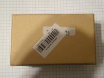 Box it arrived in | 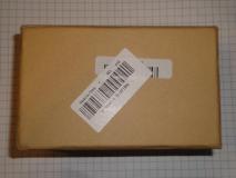 Box it arrived in | 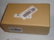 Box it arrived in | 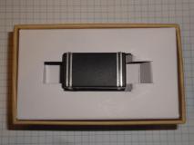 Box it arrived in |
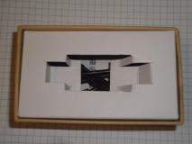 Box it arrived in | 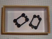 Box it arrived in | 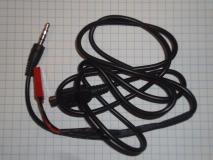 Original wiring | 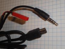 Original wiring |
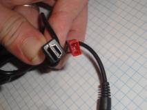 Original wiring |
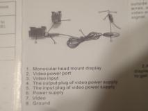
The box contained also a manual. It summarizes the parameters and the wiring. The wiring is however different than the reality.
 Manual | 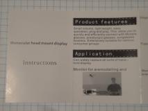 Manual | 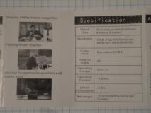 Manual | 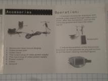 Manual |
 Manual | 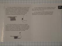 Manual | 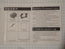 Manual |
The display unit is a little box, 36x24x21 mm. On its left side there is a mini-USB connector, used for powering the unit and video input.
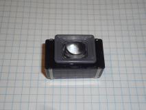 Unit | 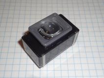 Unit | 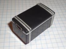 Unit | 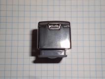 Unit |
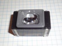 Unit | 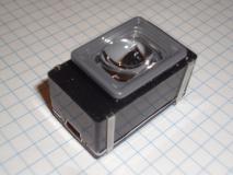 Unit | 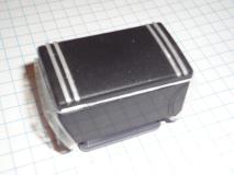 Unit |
The back of the unit is held in place with a pair of transparent rubber bands. After pulling them aside, the back can be popped off with ease. Inside, there is a controller board that's attached with a flexible ribbon cable to the display unit.
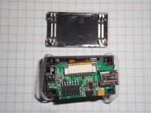 Unit, opened | 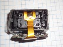 Unit, opened | 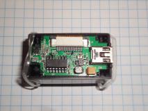 Unit, opened | 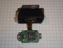 Controller board |
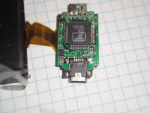 Controller board | 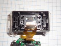 Display back | 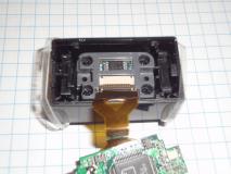 Display back | 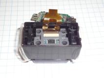 Display back |
 Display inside | 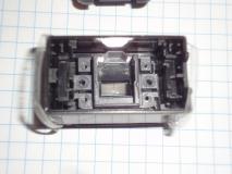 Display inside | 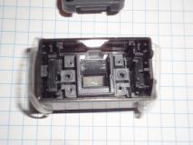 Display inside |
The unit is based on the Terawins T118B controller chip. T118 family of chips is very common in various devices utilizing LCD display panels with analog video inputs.
The controller chip uses a 27 MHz crystal, has 64-pin LQFP package, and requires 1.8V and 3.3V power.
The chip supports on-screen display functions. This may be useful for text-over-video overlays. The chip also
has a versatile VBI teletext
data decoder, opening more possibilities
of e.g. telemetry overlays encoded into the video without having to tamper with the video itself.
The chip interfaces with an optional microcontroller via two-wire interface (I2C?).
The chip supports image mirroring, via the panel scanning directions through register 0xE1. This could allow adjusting the image from cameras attached to inverting optics.
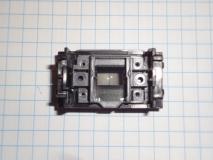
The lens is a fairly crappy plastic lens.
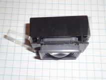 Lens | 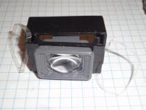 Lens | 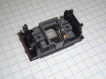 Lens assembly | 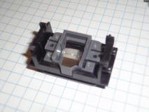 Lens assembly |
 Lens assembly | 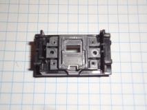 Lens assembly with light diffuser |
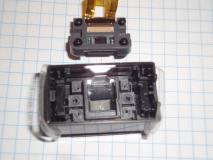
The display is a very tiny liquid crystal on silicon one, the FLCOS technology. It is reflective, the illumination
is provided with a RGB LED. The LED is shining through a little diffuser module.
The casing is a regular plastic box. Nothing special to see here.
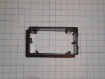 Casing outside | 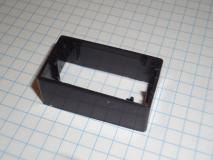 Casing outside | 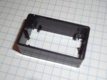 Casing outside | 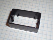 Casing outside |
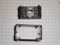 Casing | 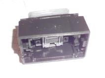 Casing with lens and diffuser | 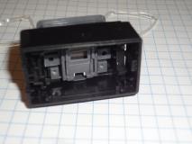 Casing with lens and diffuser | 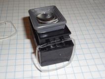 Casing with lens and diffuser |
The cable has to be modified. The stock one had a weird battery connector. (WARNING! The red and black cable were swapped, the red was ground and black was positive. Never assume the color assignments! Fortunately the device survived a short time of swapped polarity.)
A USB-A connector was attached for the ease of powering the device from any USB port, charger, or portable power bank.
The 4-pin jack connector had to be also removed and swapped with a RCA jack, matching the video output of common video players, set top boxes, and a Raspberry Pi B. The latter was used for testing.
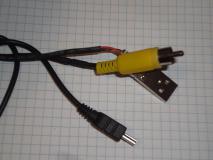 Modded cable | 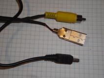 Modded cable | 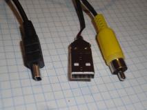 Modded cable | 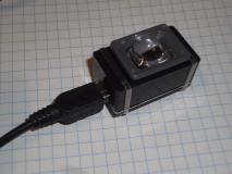 Attached cable |
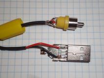 Modded cable, wire attachments | 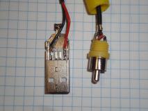 Modded cable, wire attachments |
The display was tested on a TV settop box output briefly, but primarily with a Raspberry Pi video output. The default font size is unreadable on both PAL and NTSC mode in default resolution.
On the small font display there is a piece of hair. This had to be removed later by taking the display apart again and blowing the contamination off.
The lens is unbelievably lousy, even more than what could be expected from a moulded plastic. The display is deformed, only the center area is somewhat sharp and the edges are blurred, and image on the edges is rainbowed.
The console blanks out after a couple minutes. This may be annoying. The behavior can be disabled by an escape code, which also wakes up the console (works also from a SSH session or a serial console):
echo -ne "\033[9;0]" > /dev/tty1 echo -ne "\033[9;0]"Number 0 disables blanking. Other numbers set the timeout in minutes.
echo 0 > /sys/class/graphics/fb0/blankbut it doesn't seem to actually work.
It's said blanking can be disabled altogether by appending consoleblank=0 to kernel bootargs. Doesn't seem to work with config.txt.
Uses setupcon. If not present, install via apt-get install console-setup.
cd /usr/share/consolefonts setfont Uni<something>in /boot/config.txt:
Resolution 320x240, NTSC, 16:9:
sdtv_mode=0 sdtv_aspect=3 framebuffer_width=320 framebuffer_height=240Make the screen larger, using more of the display area, by lowering overscan:
overscan_left=-24 overscan_right=0 overscan_top=-24 overscan_bottom=-24The stock cable was found lacking - the USB-mini connector was too long and was getting in the way. A different cable, with different length too, had to be made.
The connector pinout was obtained with a multimeter, using a whisker wire as a probe to touch inside the miniature USB connector.
The miniUSB connector has five pins on the connector side, but only one on the cable/solder side. The missing pin was found to be the ID, the one that in microUSB pinout is between D+ and ground.
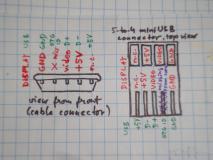 Connector pinout |
The new cable was made from a length of thin coax for the analog video, and a two-strand wire for the power, attached together by regularly spaced pieces of a heat-shrink tube.
The power and video may be possible to multiplex in the same cable using capacitive/inductive separation of the AC and DC components.
The cables were soldered to the miniUSB connector according to the pinout. The metal cover of the connector was partly cut on the sides with a Dremel wheel and then bent to shape. The cables then were attached with hot-melt adhesive, and more adhesive was used to hand-mould the connector body and to protect the pins and wires.
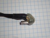 Connector, side view | 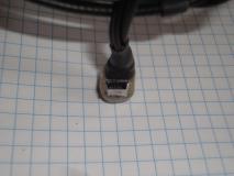 Connector, front view | 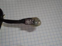 Connector, bottom view | 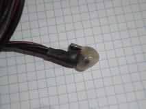 Connector, top-side view |
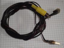 Entire cable |
The power connector was made from a very cheap USB-A connector bought in bulk from China, to assure their availability in the workshop. This connector lacks any housing, so hot-melt adhesive was again used to mould its body.
The positive and negative side of the connector are marked with red and blue color. This marking is done on most of the stocked connectors, to eliminate having to look up the pinout and to reduce wiring errors.
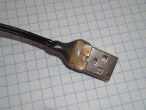 USB power connector | 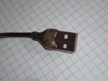 USB power connector | 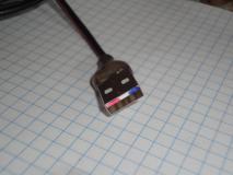 USB power connector |
The connector now sticks out only minimally and folds over the display housing, facilitating cable direction over the ear when the display is located over right eye.
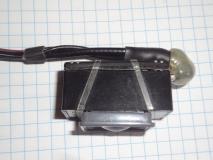 Cable, attached | 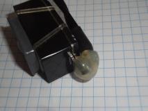 Cable, attached | 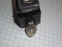 Cable, attached | 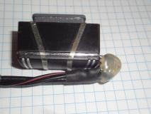 Cable, attached |