Krizik RT2,5 Variac Mod
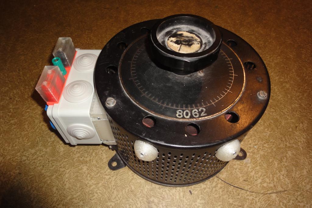
Original variac
An ancient Křižík RT2,5 variable autotransformer (variac) was
inherited. The unit is a fairly historical piece, dating perhaps to later 1950's. The variac was made in the
Křižík Smichov company (later overtaken by ZPA Prešov concern, which took over the sortiment of the
old Křižík corporation sometime in 1950s or 1960s.)
(variac) was
inherited. The unit is a fairly historical piece, dating perhaps to later 1950's. The variac was made in the
Křižík Smichov company (later overtaken by ZPA Prešov concern, which took over the sortiment of the
old Křižík corporation sometime in 1950s or 1960s.)
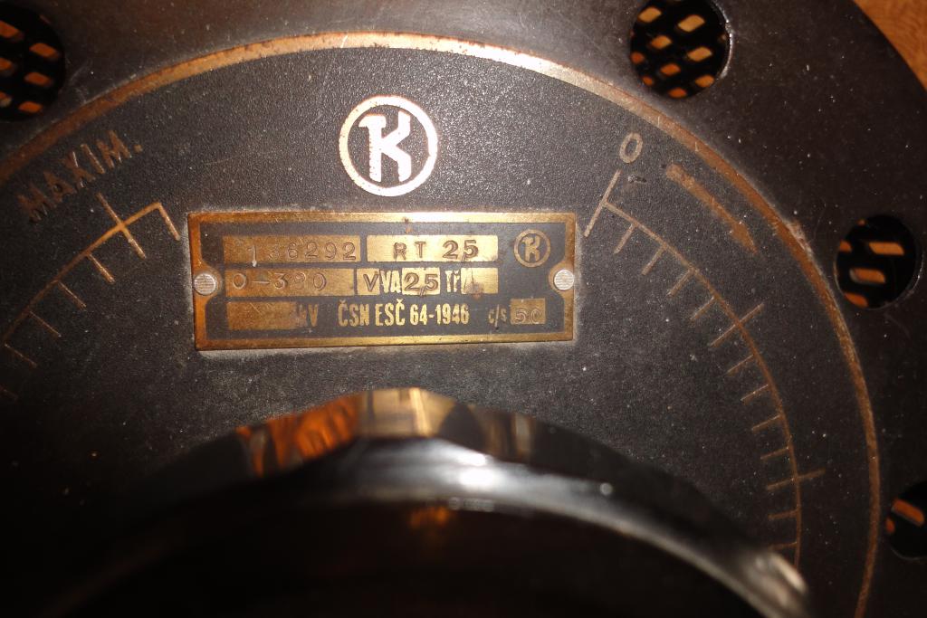
The variac is rated for 380 volts and 2.5 amps, in intermittent use. For permanent deployment it has to be
derated to 75%, roughly 1.9 amp. The regulation is stepwise, with steps of about 0.4% (the J variant provides
finer steps at 0.02%; alas, this model is not the J one).
The output voltage is in 0..100% input range. No provision for higher-than-input voltage. This is a limitation
of the RT2.5 model. The RAT10 model allows going to 250 volts of output.
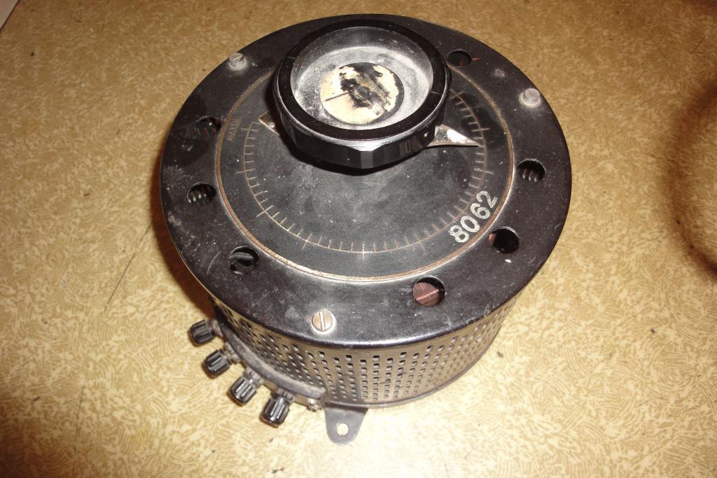
The variac is rather unwieldy cylinder with diameter of 223 mm, height of 155 mm (without the knob), and
weight of 10 kilograms. This baby is heavy.
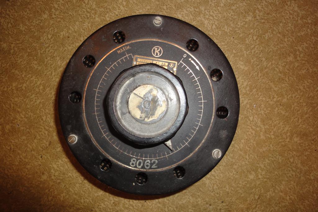
Compared with photos of the same type from various online auctions, this is an earlier model. The top
dial is deeply etched from brass; the later models have it made from anodized aluminium.
There is a manual available, dated to May 1957.
The frequency rating is in cycles per seconds, the device
predates mass adoption of the Hertz unit. Hertz was adopted by CGPM in 1960 and largely replaced c/s by
1970s, it is therefore a surprisingly young unit.
There are also manuals for other similar variacs by the same company:

Variac | 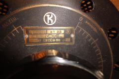
Variac | 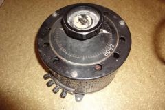
Variac | 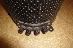
Variac |
Variac | 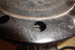
Variac | 
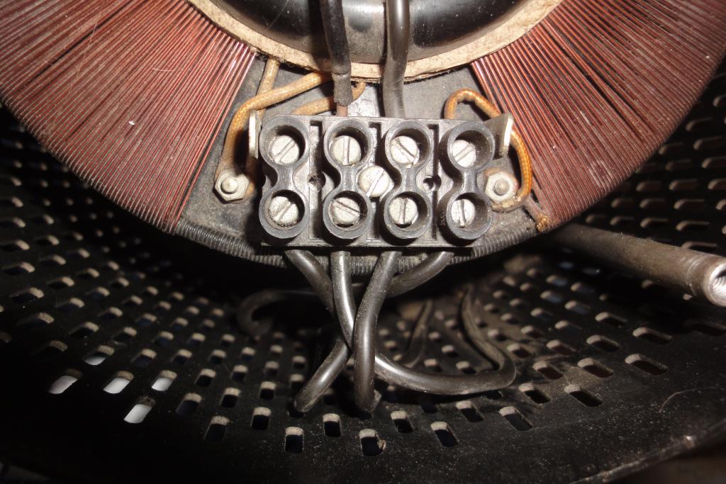
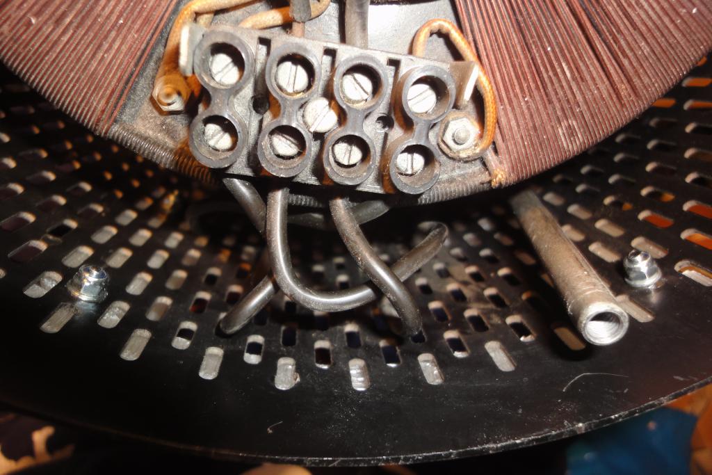
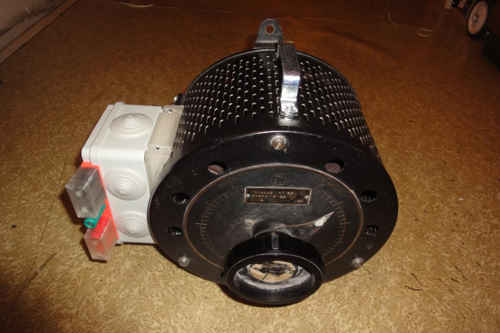
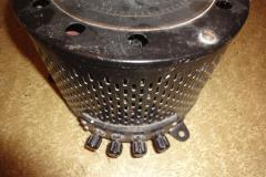
Variac, uncovered | 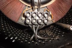
Variac, uncovered |
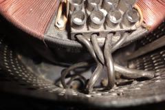
Variac, uncovered | 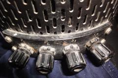
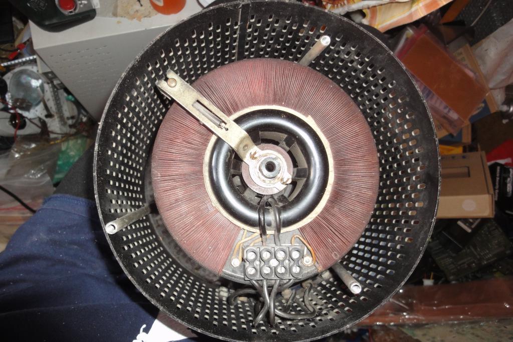
Variac binding posts | 
Variac internal wiring | |
Modifications philosophy
To facilitate use in a modern workshop, a box with input and output socket, switches, and
binding posts was added. Also a carrying handle was added to facilitate transportation.
As the device is a historical piece, invasive modifications were shunned. Everything is attached
to the original device using the holes already existing in its chassis, and electrical connections
are done via its original binding posts.
Carrying handle
To facilitate easier transportation, a carrying handle was added to the device's top.
An off-the-shelf metal handle was chosen on the basis of availability. It is designed for countersunk M4
screws, but the requirement to not invasively modify the original chassis led to using somewhat
wimpy M3 screws, with large washers and Nyloc nuts.
Connection box
For the input and output sockets, the binding posts, and the associated wiring, an installation
box made of grey electrical grade ABS was chosen on the basis
of its size and availability.
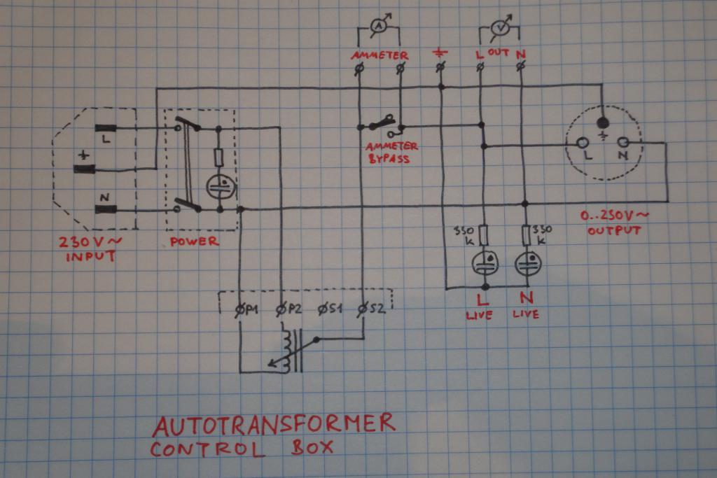
Wiring
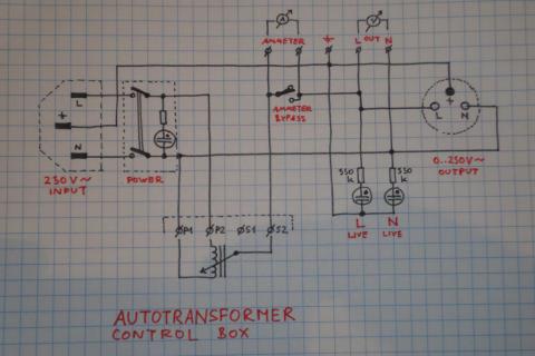
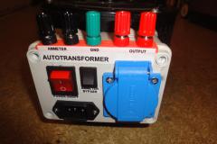
The power is fed to the input [link?:IEC 60320] C14 power socket, chosen for its common occurrence on
personal computer equipment and the associated availability of power cords. From there, it is connected
to a DPST switch with an integrated neon lamp indicating presence of power on the output.
The output is realized as a pair of binding posts, and a lidded
CE 7/5 socket, with the
left pin designated as L and right as N.
The L power line is led to the P2 binding post on the variac.
The N power line is led to the P1 binding post on the variac, and to the N output binding post (the right one)
and the N terminal of the output socket.
The brush of the variac (the S2 binding post) is connected to the left ammeter post, and the
ammeter bypass switch. The other end of the bypass switch is connected to the right ammeter post,
and the left binding post (L) of the output.
The safety ground is connected to the ground binding post (green) and the ground pin of the output socket.
(WARNING: the transformer's own chassis is not grounded and is left floating.)
A pair of neon lamps with series 330kΩ resistors is attached to the L and N output
terminals and connected to the safety ground pin. In this area it is commonly assumed that the L wire is
on the left side and N on the right side. The actual socket wiring, socket adapters and extension cords
are sometimes wired in a crossed way. Operator assuming that N is not live then can encounter a nasty
surprise - what a buzz. The neon ligth indicates which one of the terminals has to be handled with utmost
care.
The neon lamps may trip some more sensitive ground fault interrupters. The current
is limited to below 1 milliamp, which should not be enough for most but may be sufficient for some.
A pair of binding posts is dedicated for attachment of an ammeter. These terminals are bypassed with a
dedicated switch for the cases when nothing is attached. Another pair of posts facilitates attachment
of a voltmeter. This allows easy attachment of instrumentation without excessive ad-hoc wiring, for
more comfort and safety of the operator.
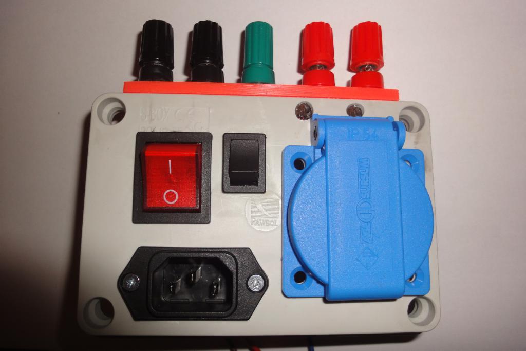
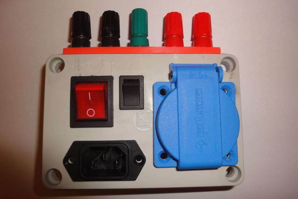
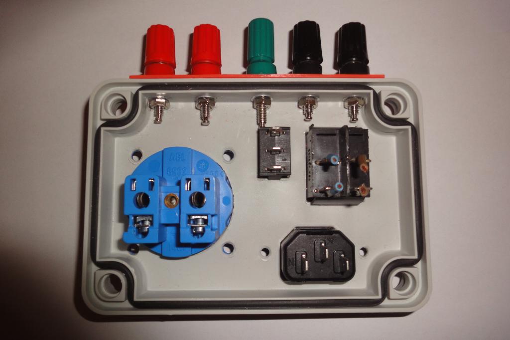
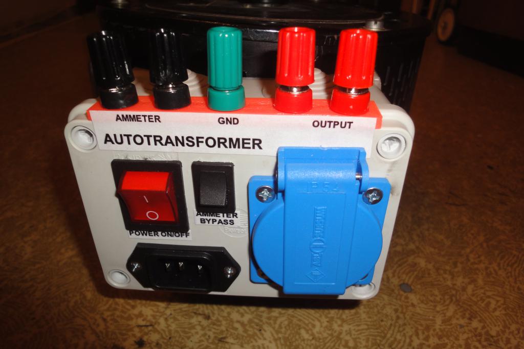
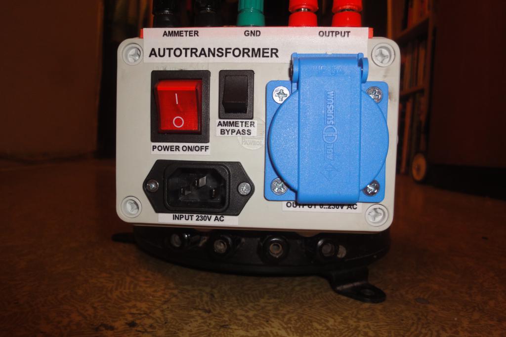
The box's lid accommodates the input IEC socket, the output European socket with a lid, the
main power switch, the ammeter bypass, and the binding posts. Everything was chosen to be fitted to the
lid to avoid having too much of wiring between the top and bottom parts of the box, due to ease of
making.
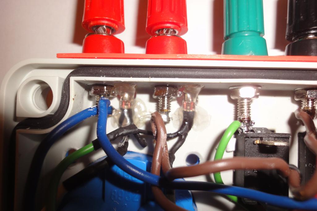
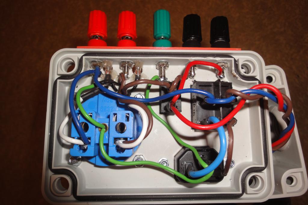
Lid wiring | 
Neon bulbs attachment | 
Outside of the lid | 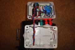
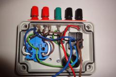
Box wiring |

Box wiring | | | |
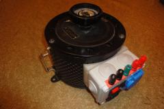
Mounting adapter
The variac is a cylinder. The electronics box has a flat bottom.
To facilitate fitting of a flat surface to a curved surface, an adapter had to be designed.
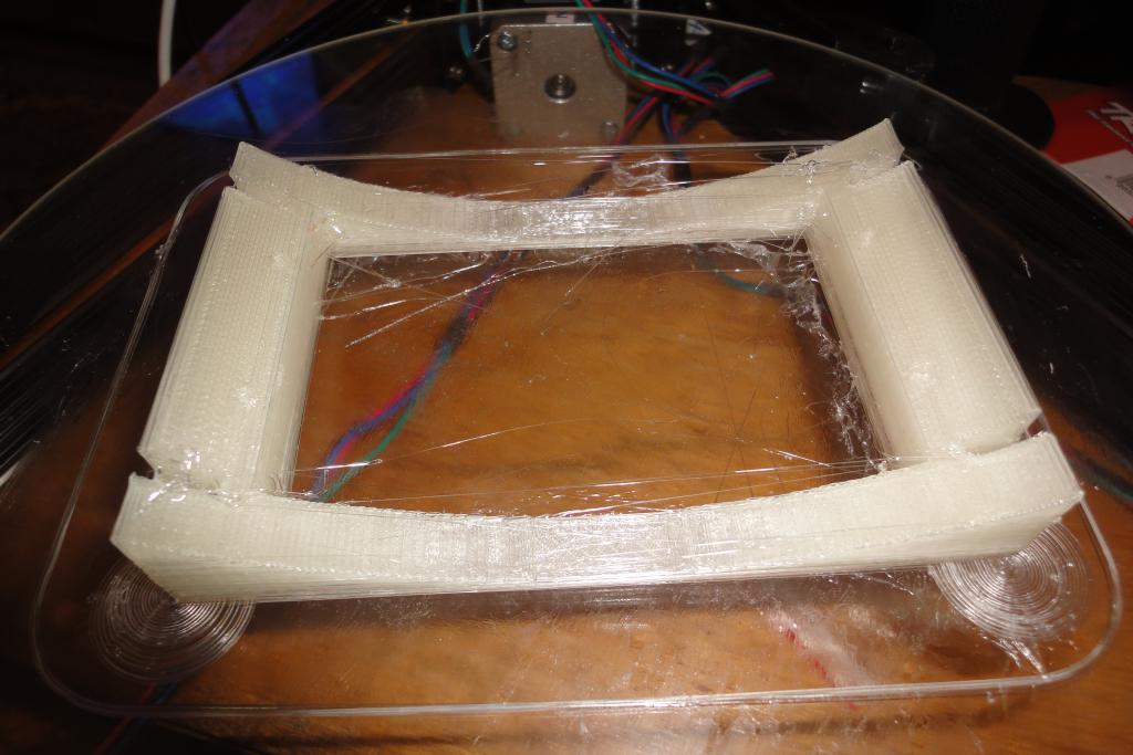
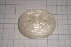
3D printing was chosen due to a recent availability of a Kossel XL 3D printer. The object was
designed in OpenSCAD, rendered to STL, converted to G-code via Slic3r and printed via Pronterface.
PLA filament was used, at temperature of 205 °C.
Coarse resolution with 0.4 mm layers was chosen for the reason of sane printing time.
Due to a measurement error, the cylinder diameter was defined as 218 mm which was a bit smaller than the
real 223 mm; the error however turned out to be unimportant. Due to the difficulties of accurately calculating
the positions of the mounting holes, flat slits were instead cut into the material, perpendicular to the
cylinder wall. The slits were widened on top to accommodate a M3 screw with a washer, to spread the load over
larger area.
Because of lack of familiarity with the technology, there were hiccups during the printing. First attempt
failed, second attempt got filament seizing in the bowden a few millimeters of thickness in; it was decided
to go with poorly printed layer as that part of the design was to be loaded in compression anyway. The printing
was interrupted, the head manually lowered the fraction of millimeter that was lost, the bowden was disconnected
and deformed length of the filament removed (too much pressure on the actuator bites its teeth too deep into
the filament and the deformation jams the filament in the bowden tube). Filament was then manually fed into the
extruder and printing was resumed. The affected layer is structurally weak and ugly but does not impair the
part's performance.
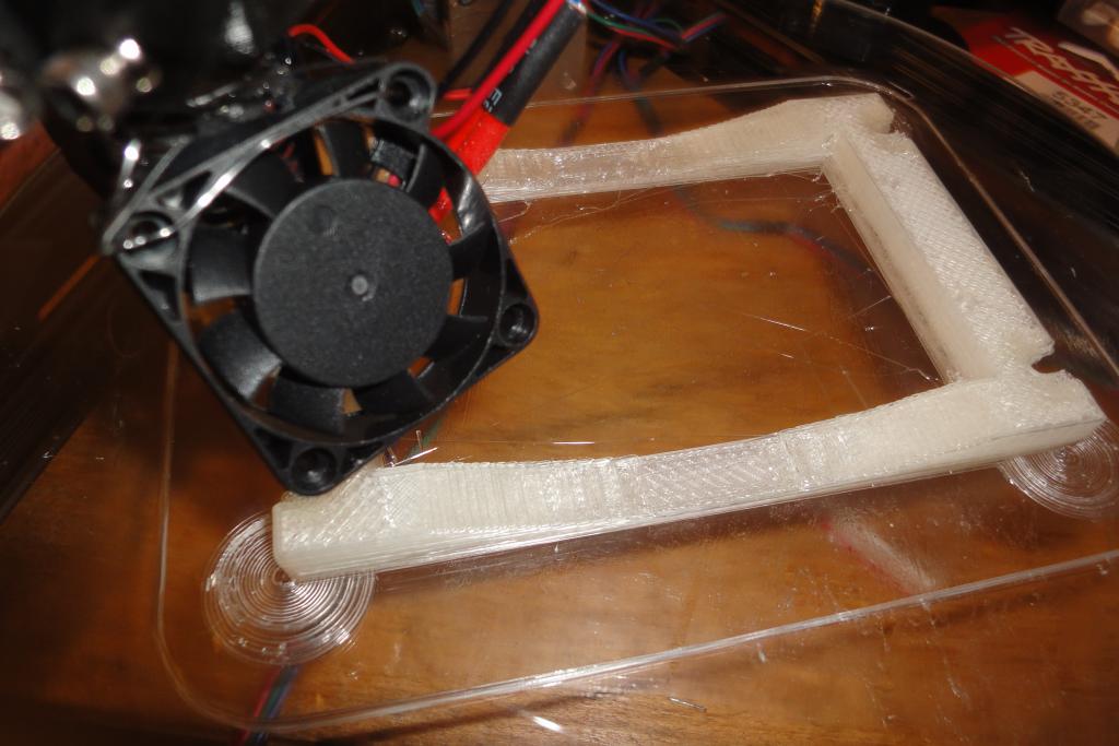
The part's edges lifted from the printer bed; a common issue that will have to be addressed. At first attempt
the lifting was catastrophical, at the second attempt circular pads at the base layer were added that improved
but not completely eliminated the situation.
The printing took about 3 hours.
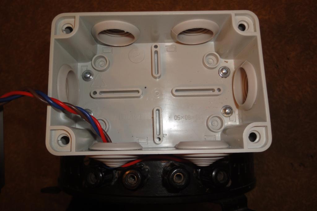
After printing, the thin holes for attachment to the box were drilled through with a 1mm drill bit. The box was
mated to the adapter and the holes then were drilled again, through the box. Then they were enlarged to 3mm at
the box and 1.5mm on the adapter.
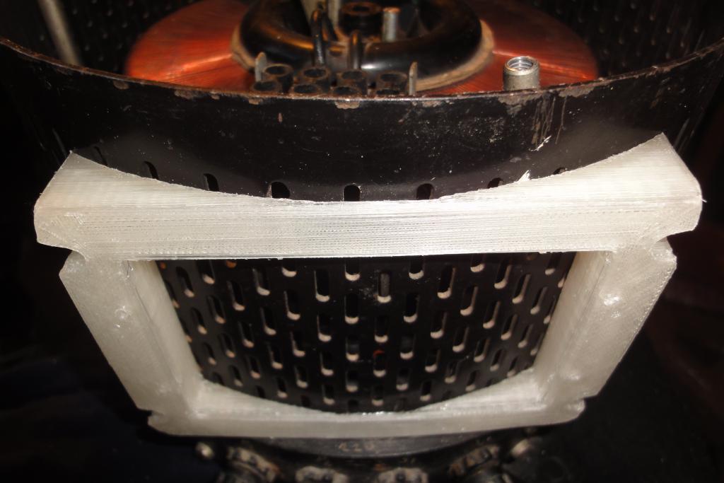
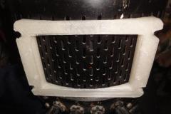
The adapter was attached to the transformer's body, just above its own binding posts, using four M3 screw
with washers and Nyloc nuts. The box was attached to the adapter using four wood screws with washers.
Due to a small assumption error, the mounting holes were offset between the left and right side. The adapter
(and the box) is therefore attached in a slightly skewed way.

Adapter printing | 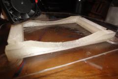
Adapter printing | 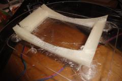
Adapter printing | 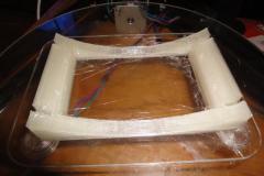
Adapter printing |
Adapter attachment | 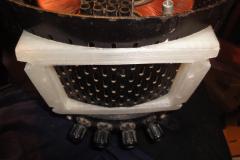
Adapter attachment | 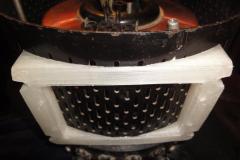
Adapter attachment | |
Panel cutouts
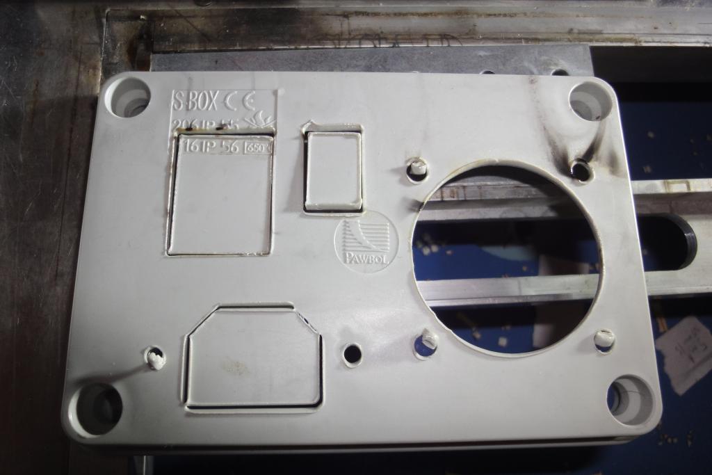
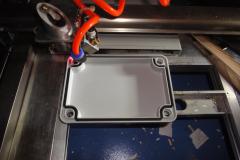
The sockets and switches have to be placed in fairly large rectangular cutouts. To eliminate the need for
manually cutting the holes using a hot knife and/or a Dremel tool, a laser cutter was employed. The lid was
measured and approximately modeled in OpenSCAD, the switches and sockets were also modeled, assembled on the
panel, then the outlines of the holes were exported to DXF. Then they were laser-cut.
The electrical-grade ABS tends to melt under the laser beam and widen the kerf and lift its edges. At 12 mA and
5 mm/s the beam burned through 2.5-3mm plastic almost entirely at a first pass. The speed was too slow and
too much energy was delivered to the edges of the cut, which caused the melting/widening issues. Finishing cuts
were therefore done in two more passes at higher speed (15 mm/s). Lesson learned - use fastest speed achievable
and more passes instead. The plastic also generates a copious amount of smoke, necessitating the use of air assist
at least to protect the laser's lens from deposition of residues. Some soot marking was observed on the bottom side,
suggesting a need for some surface protection (peel-off paint? weakly adhesive foil or paper?).
The bottom side (box's outer side) hole edges had to be chamfered. That was easily done with a chamfer bit
for the round holes, and an edge of scissors for the large round hole and the square ones.
Lid laser cutting | 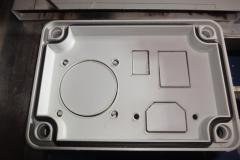
Lid laser cutting | 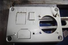
Lid laser cutting | |
The switches and the IEC socket fit the holes neatly. The hole for the CE7/5 socket was a little too small and
had to be enlarged with a few brushes of a round file.
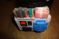
The binding posts are placed on the top side of the lid. As the lid is chamfered, an adapter had to be made
to provide them with a flat surface to mate against. 3D printing was chosen for the availability and simplicity.
After attaching to the top of the lid, holes were drilled using the printed holes as drilling guides. M4 screw
was used after drilling the first hole to maintain alignment. The adapter is held in place by the binding posts.
Labels were drawn in HTML/CSS, printed on a laser printer, laminated with a plastic spray-paint,
layered with doublesided adhesive tape, cut, and placed on the front panel.
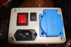
Lid populated with parts | 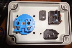
Lid populated with parts | 
Lid with binding posts | 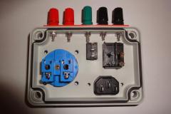
Lid with binding posts |
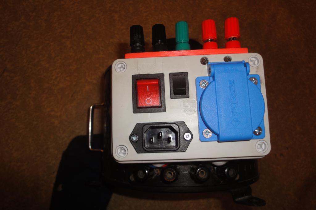
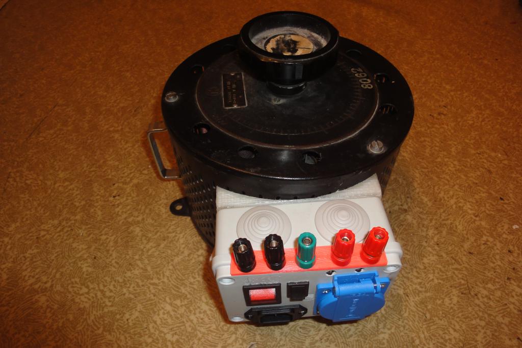
Finished assembly

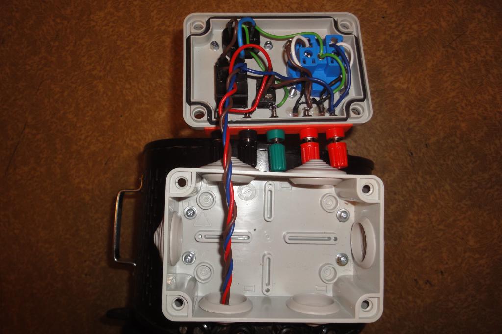
Wiring attachment to variac | 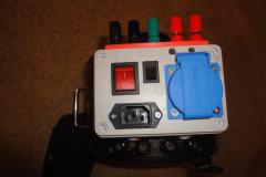
Finished assembly | 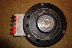
Finished assembly | 
Finished assembly |
Finished assembly | 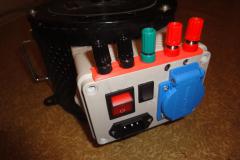
Finished assembly | 
Labels | 
Labels |
Finished case with labels | 
Finished case with labels | 
Finished case with labels | |
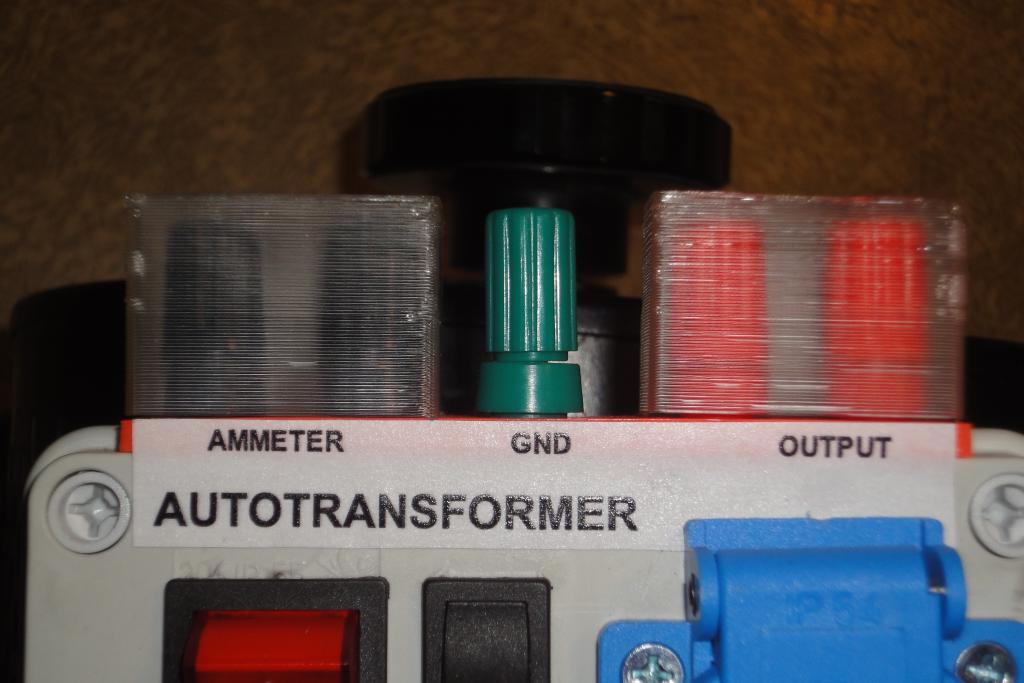
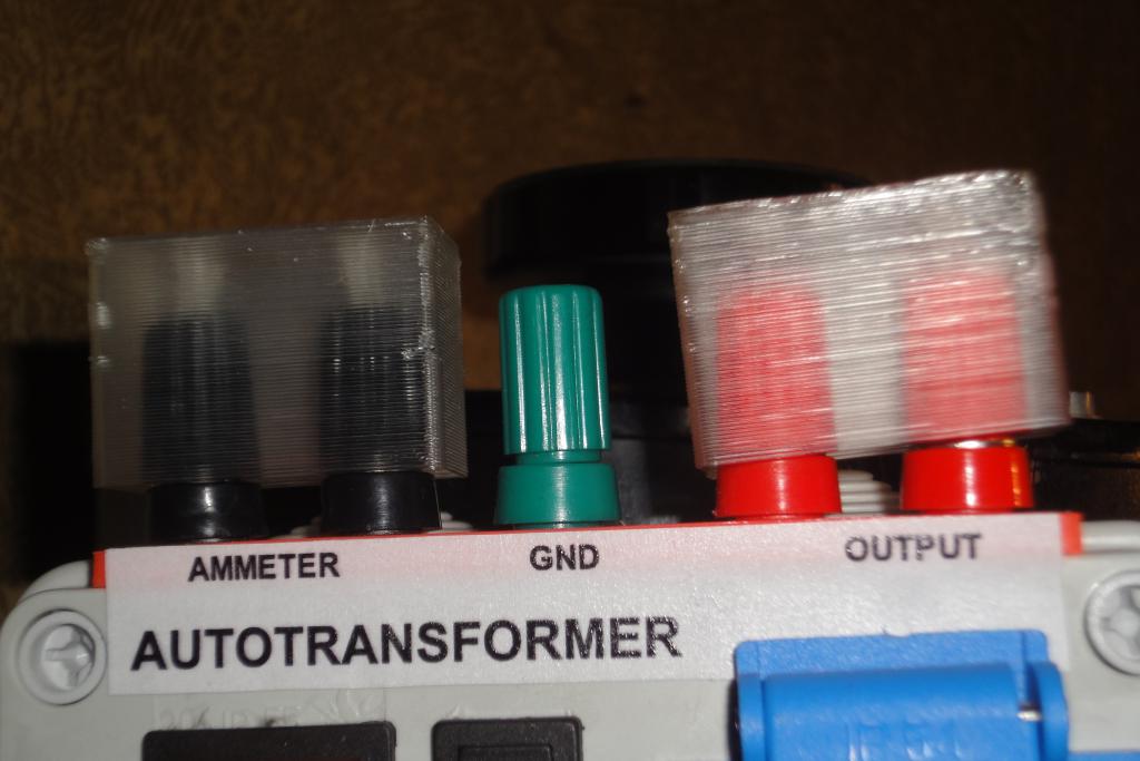
Addition: Binding posts covers
It was found that the binding posts are somewhat too exposed, allowing easy unintended touch of
live parts. A part was designed in OpenSCAD. Two were 3d-printed, and inserted into the binding post
banana plug holes.
See also: hw_3d_BindingPostCovers , the whole separate project.
Binding post covers | 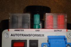
Binding post covers | 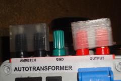
Binding post covers | |
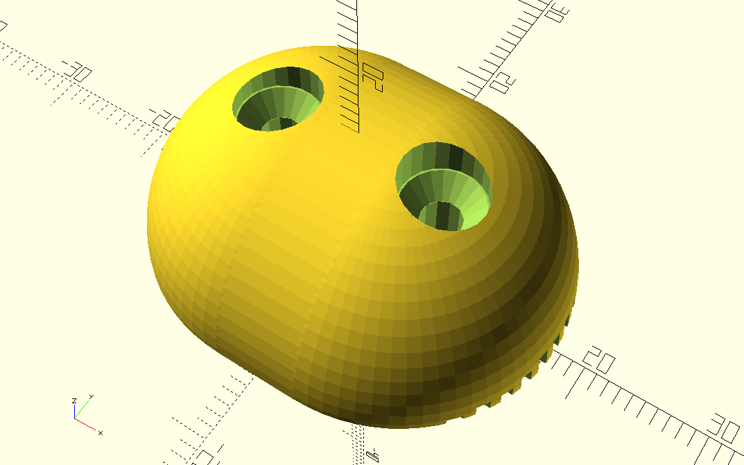
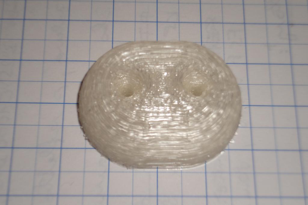
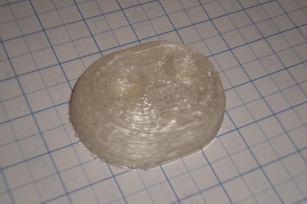
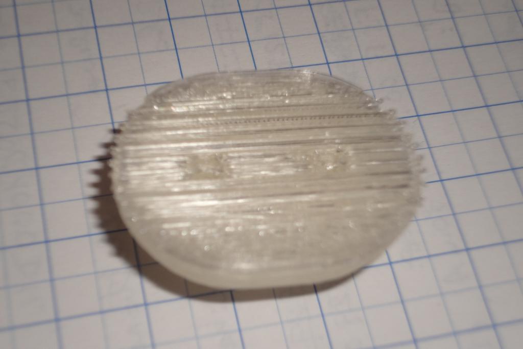
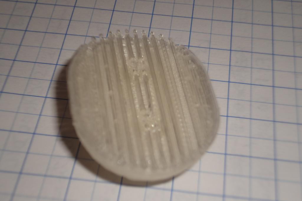
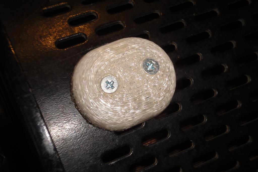
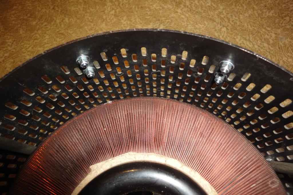
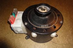
Addition: Feet
Due to the addition of the carrying handle, the variac tends to be laid on its bottom quite often.
The round bottom causes it to roll to side, until one of the base pads stops the rotation. Addition
of small feet to keep it upright was found to be desirable.
The feet were designed in OpenSCAD, 3d-printed, and attached with pairs of M3 screws to the vent
holes in the original chassis. The printouts took about 20 minutes per piece. Four layers of outer shell
were used, together with 50% density honeycomb fill, to achieve high strength and impact resistance.
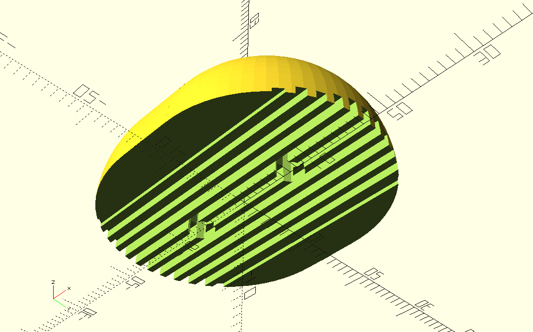
The bottom of the feet is supposed to mate against a round chassis, and at the same time it should be
flat to lay well on the printer bed. The thermoplasticity of the material was exploited. Ribs were made
to the flat bottom. After printing, the bottom with the ribs was heated with a small torch until the
ribs softened, then the part was pressed against the curved surface and moved back and forth to smooth
it. A perfectly mating surface was achieved. The outer surface was also heated with a torch again and slowly
allowed to cool, with hope that the printed layers will melt together on the surface.

Rendered variac foot | 
Rendered variac foot | | |
Foot, freshly printed | 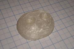
Foot, freshly printed | 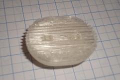
Foot, freshly printed | 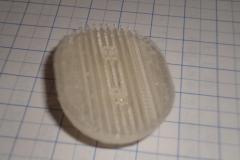
Foot, freshly printed |
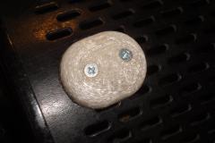
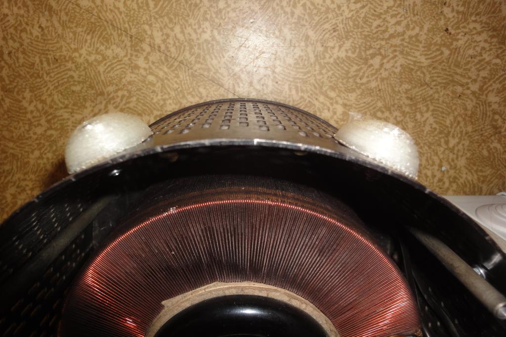
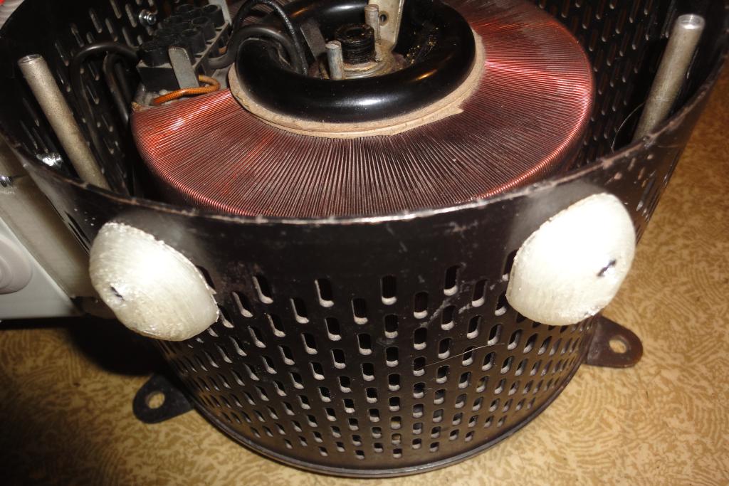
Foot, attached | 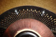
Attached feet | 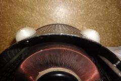
Attached feet | 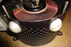
Attached feet |
Attached feet | 
Standing variac | 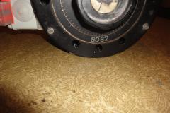
Standing variac | 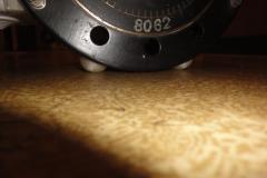
Standing variac |
TODO
- Schematics printout label
- Better documentation of the variac's own internal wiring
- Warning label about ungrounded chassis
- Warning label about 2.5 amps current limitation
- Possibly adding a small voltmeter and ammeter to the box
| If you have any comments or questions about the topic, please let me know here: |